background image

Page 59

Version 2022-12-20

SEDM - Smoke extraction damper - multi

TPM 156/22

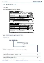
VII. PRODUCT DATA

Data label

Data label is placed on the damper casing (example)

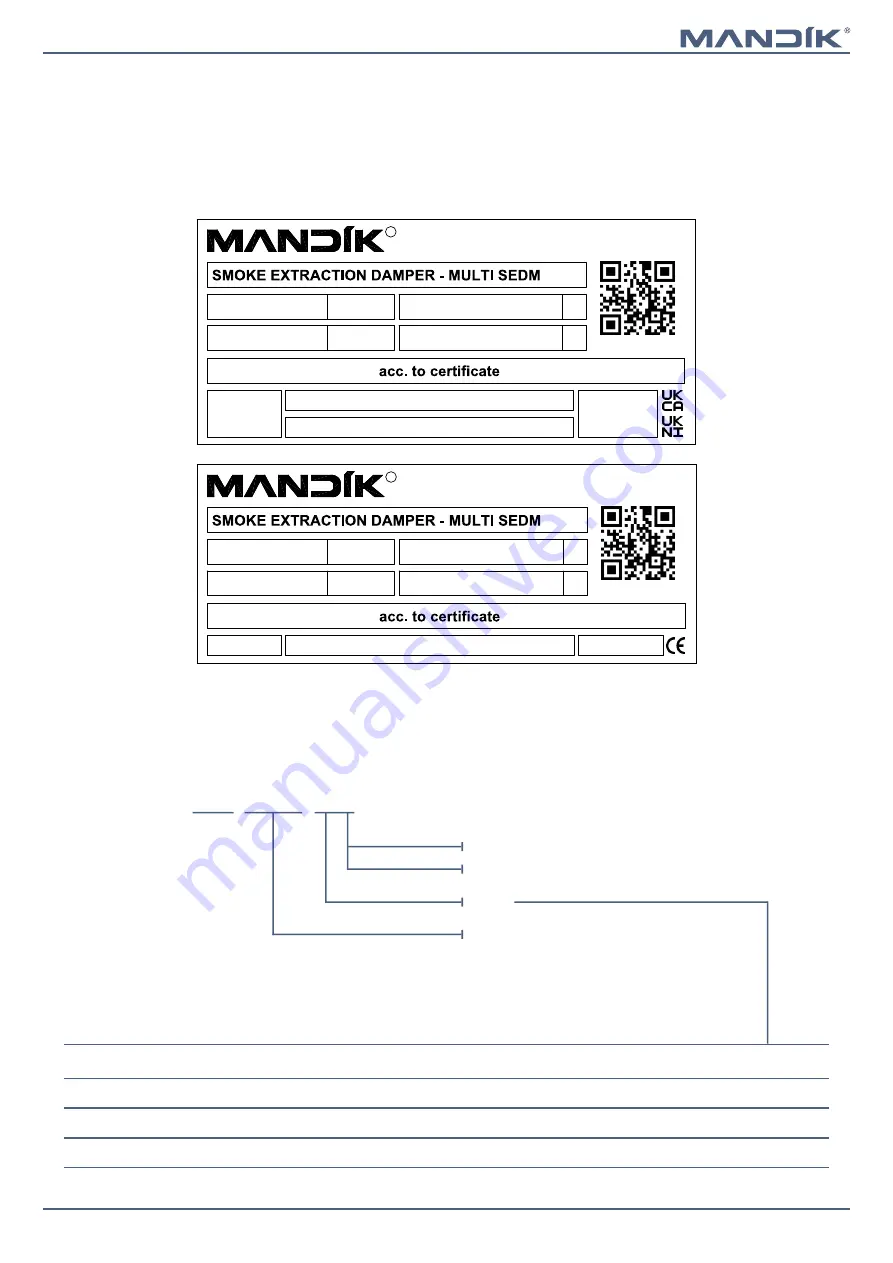
VIII. ORDERING INFORMATION

Ordering key

without flanges

P

 - with flanges

SEDM   180x355 - .44/P

EXAMPLE:
SEDM 180x355 - .44/P

 - 180x355-damper size, .44-damper design, P-with flanges

design

size AxB

Dampers design

Additional digit

with actuating mechanism BEN, BEE, BE, InMax 50.75-S for 230V

.44

with actuating mechanism BEN, BEE, BE, InMax 50.75-S for 24V

.54

with actuating mechanism BEN (BEE)-SR for 24V

.65*

*  Design .65 is not available by using actuating mechanism BE, InMax 50.75-S

WEIGHT (kg):

Dobříšská 550, 267 24 Hostomice, Czech Republic

MANDÍK, a.s.

ACTUATING SYSTEM:

YEAR/SER.NO.:

DIMENSION:

TPM 156/22

R

FIRE PROTEC. CLASS:

MANUAL

Certificate UKCA No.: 0832-UKCA-CPR-P1006, DoP: PM/SEDM/02/22/1

EN 12101-8:2011

Certificate UKNI No.: 0832-UKNI-CPR-P1001, DoP: PM/SEDM/02/22/1

WEIGHT (kg):

Dobříšská 550, 267 24 Hostomice, Czech Republic

MANDÍK, a.s.

ACTUATING SYSTEM:

YEAR/SER.NO.:

DIMENSION:

TPM 156/22

R

FIRE PROTEC. CLASS:

MANUAL

Certificate CE No.: 1391-CPR-2021/0130, DoP: PM/SEDM/01/22/3

EN 12101-8:2011

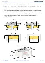
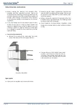
Summary of Contents for SEDM

Page 1: ...dik cz Manufacturer MANDIK UK Ltd 130 Aztec West Bristol BS32 4UB United Kingdom Tel 44 117 4526376 E Mail help mandik co uk Authorized representative SEDM Smoke extraction damper multi Technical Docu...

Page 2: ...e compartment 26 Installation in gypsum wall construction of fire compartment 27 Installation in solid ceiling construction of fire compartment 28 Installation in battery 29 Suspension systems 33 Duct...

Page 3: ...n be connected to the smoke exhaust ducts tested according to EN 1366 8 or they can be installed in or on the construction of the fire compartment Dampers can be delivered with or without flanges Damp...

Page 4: ...n the adjoining cable duct which passes through an opening made in the wall of the insulated cover box when installing the damper or when connecting the actuator power cable The power and control cabl...

Page 5: ...sioning 6 VA Imax 8 2 A 5 ms 6 5 VA Imax 8 2 A 5 ms 7 VA Imax 4 A 5 ms Protection class III III II Degree of protection IP 54 Adjustment time for 95 30 s Ambient temperature Storage temperature 30 C 5...

Page 6: ...n IP 54 Adjustment time for 95 60 s Ambient temperature Storage temperature 30 C 55 C 40 C 80 C Connection drive auxiliary switch Cable 1 m 3 x 0 75 mm2 Cable 1 m 6 x 0 75 mm2 BEE 24 ST with plug conn...

Page 7: ...7 9 A 5 ms Protection class III II Degree of protection IP 54 Adjustment time for 95 60 s Ambient temperature Storage temperature 30 C 55 C 40 C 80 C Connection drive auxiliary switch Cable 1 m 3 x 0...

Page 8: ...on IP 66 Adjustment time for 95 60 s Ambient temperature Storage temperature 40 C 50 C 40 C 70 C Connection Cable 1 m 0 5 mm2 SCHISCHEK 50 75 N m 1 2 3 4 24 230 VAC DC 1 2 3 4 5 6 heater PA 85 5 PE In...

Page 9: ...damper control panel to BS ISO 21927 9 Cable glands Comms cable Damper control module PCB mounted on plastic rail Earth stud 230v 50hz 3A fused supply by others Switches 6 core Drive open close 230v...

Page 10: ...with flanges Dimensions with actuating mechanism InMax 50 75S If it is necessary arbitrary flange could be removed 1 SEDM 2 Actuating mechanism 3 Damper blade 4 Access door inspection cover 5 Flange X...

Page 11: ...e specified in chapter Technical parameters see pages 12 to 23 For damper with flanges the open damper blade overlaps the damper body from dimension B 355 by the value f or e and f These values are sp...

Page 12: ...83 6 0 0759 BELIMO BEE 25 N m 900 111 279 61 229 83 4 90 5 0 0869 1000 161 329 111 279 89 6 97 2 0 0979 200 x 180 39 6 42 7 0 0091 BELIMO BEN 15 N m 200 40 9 44 1 0 0117 225 42 4 45 8 0 0150 250 44 0...

Page 13: ...250 47 3 51 2 0 0252 280 49 3 53 3 0 0306 300 50 6 54 8 0 0342 315 51 7 55 9 0 0369 355 6 5 54 4 58 7 0 0441 400 29 57 4 62 1 0 0522 450 54 4 60 8 65 7 0 0612 500 79 29 64 1 69 4 0 0702 550 104 54 67...

Page 14: ...59 69 8 75 5 0 1035 600 129 79 72 5 78 4 0 1127 630 144 94 74 6 80 6 0 1196 650 154 104 76 1 82 2 0 1242 700 11 179 129 79 4 85 8 0 1357 710 16 184 134 80 1 86 6 0 1380 750 36 204 154 82 8 89 4 0 1472...

Page 15: ...7 5 0 1967 BELIMO BEE 25 N m 900 111 279 61 229 97 4 105 1 0 2252 1000 161 329 111 279 104 6 112 8 0 2537 400 x 180 49 7 53 8 0 0231 BELIMO BEN 15 N m 200 51 2 55 5 0 0297 225 53 0 57 5 0 0380 250 55...

Page 16: ...0 0387 225 56 9 60 6 0 0495 250 58 9 62 7 0 0602 280 61 3 65 2 0 0731 300 62 9 66 9 0 0817 315 64 0 68 1 0 0882 355 6 5 67 1 71 5 0 1054 400 29 70 8 75 2 0 1247 450 54 4 74 6 79 2 0 1462 500 79 29 78...

Page 17: ...54 87 3 94 0 0 2156 560 109 59 88 1 94 9 0 2205 600 129 79 91 5 98 4 0 2401 630 144 94 93 9 101 1 0 2548 650 154 104 95 6 102 9 0 2646 700 11 179 129 99 8 107 3 0 2891 710 16 184 134 100 5 108 1 0 294...

Page 18: ...LIMO BEE 25 N m 800 61 229 11 179 114 8 123 1 0 3864 900 111 279 61 229 124 6 133 6 0 4424 1000 161 329 111 279 133 4 142 9 0 4984 BELIMO BE 40 N m 650 x 180 61 8 67 1 0 0406 BELIMO BEN 15 N m 200 63...

Page 19: ...15 N m 200 65 4 70 9 0 0576 225 67 6 73 3 0 0736 250 69 9 75 8 0 0896 280 72 6 78 6 0 1088 300 74 4 80 5 0 1216 315 75 8 81 9 0 1312 355 6 5 79 3 85 6 0 1568 400 29 83 4 90 0 0 1856 450 54 4 87 8 94...

Page 20: ...6 8 0 2847 550 104 54 103 9 111 8 0 3212 560 109 59 104 9 112 7 0 3285 600 129 79 108 7 116 8 0 3577 BELIMO BEE 25 N m 630 144 94 111 6 119 8 0 3796 650 154 104 113 6 121 9 0 3942 700 11 179 129 118 3...

Page 21: ...134 135 8 143 0 0 5580 750 36 204 154 140 2 147 4 0 5952 800 61 229 11 179 145 4 152 8 0 6417 900 111 279 61 229 156 1 163 9 0 7347 1000 161 329 111 279 166 8 174 9 0 8277 1100 x 180 83 4 87 1 0 0721...

Page 22: ...m 200 97 9 106 5 0 1197 225 101 1 109 8 0 1530 250 104 2 113 0 0 1862 280 108 0 117 0 0 2261 300 110 5 119 6 0 2527 315 112 5 121 6 0 2727 355 6 5 117 4 126 8 0 3259 BELIMO BEE 25 N m 400 29 123 2 132...

Page 23: ...279 217 9 230 9 1 2727 1600 x 180 105 7 115 1 0 1071 BELIMO BEN 15 N m 200 108 4 118 0 0 1377 225 111 9 121 6 0 1760 250 115 3 125 1 0 2142 280 119 5 129 5 0 2601 300 122 2 132 4 0 2907 BELIMO BEE 25...

Page 24: ...damper and construction wall ceiling This is the BS EN1366 2 test standard distances They are considered as minimum Actual location should be based on wall manufacturers requirements Always consult t...

Page 25: ...s 100mm thick and fire resistance EI 60 then an EI 120 S damper can be used and will be classified as EI60S Placement wall ceiling min thickness mm Filling of space between damper and wall Fire resist...

Page 26: ...duct see pages 42 to 44 Examples of anchors to the fire dividing construction see pages 39 to 41 EIS 120 Solid wall construction Ablative Coated Batt horizontal blade axis position Cover of actuating...

Page 27: ...duct see pages 42 to 44 Examples of anchors to the fire dividing construction see pages 39 to 41 EIS 120 X 100 X Gypsum wall construction Ablative Coated Batt horizontal blade axis position Cover of a...

Page 28: ...eaded rod see pages 33 to 36 6 Calcium silicate Actuator housing 7 L holder see page 37 EIS 120 Solid ceiling construction Ablative Coated Batt act mechanism above X Brackets must be mounted on sides...

Page 29: ...t be joint between damper body and floor min 75 mm and must be completely filled with gypsum Each damper must be suitably supported in each corner front and rear with temporary supports whilst being I...

Page 30: ...from edge see fig Connecting straps spacer straps screws screw connections and Promat glue K84 are not included in the delivery RESPECT JOINT POSITION Bolts and nuts shall not prevent free rotation o...

Page 31: ...floor min 75 mm and must be completely filled with gypsum Each damper must be suitably supported in each cor ner front and rear with temporary supports whilst being Installed and fire stopped final su...

Page 32: ...h cor ner front and rear with temporary supports whilst being Installed and fire stopped final supporters must be installed backto studs workor steel workas required y min 30 mm max 400 mm B A y y y B...

Page 33: ...ides location and symmetry is not a specific requirement but is preferential The dampers and duct must be suspended separately Duct from BS EN 12101 7 in Steel insulated or spray coated Number of L ho...

Page 34: ...on and symmetry is not a specific requirement but is preferential The dampers and duct must be suspended separately Duct from BS EN 12101 7 in Steel insulated or spray coated Number of L holders and t...

Page 35: ...al thread and hexagon drive Without anchor With anchor Possible examples of anchoring to the ceiling construction Follow the instructions of fixing specialist or installation company Hinge plates 2x 9...

Page 36: ...d M8 M20 3 Support HILTI MQ 41 or MQ 41 3 or equivalent 4 Bored plate HILTI MQZ L or equivalent 5 Washer for M8 M20 6 Nut M8 M20 7 Flange of SEDM 8 Flange of duct max 50 Dimension elements of the susp...

Page 37: ...bolt min M8x60 mm 2 pcs large washer M8 nut M8 or Anchor to concrete see page 35 Details and examples placing of L holder see pages 33 to 34 and 38 78 120 80 120 FOR A 500 B 500 FOR A 500 B 500 FOR A...

Page 38: ...2 Support HILTI MQ 41 or MQ 41 3 or equivalent 3 L holder optional accessories from MANDIK a s 4 Screw UNI 5x40 mm 5 M8 bolt assemply bolt min M8x60 mm 2 pcs large washer M8 nut M8 or equivalent 6 An...

Page 39: ...Anchor to concrete min M6 or Screw UNI 6x60 mm to Gypsum grid from C profile 4 Installation hols 5 M8 bolt assemply bolt M8x55 mm 2 pcs large washer M8 nut M8 Details seepages40to41 FOR A 500 B 500 F...

Page 40: ...thickness 2 mm and min width 60 mm 5 Anchor to concrete min M6 6 Installation hols 7 M8 bolt assemply bolt M8x55 mm 2 pcs large washer M8 nut M8 The method of mounting must meet the minimum requiremen...

Page 41: ...ss 2 mm and min width 60 mm 5 Screw UNI 6x60 mm 6 Installation hols 7 M8 bolt assemply bolt M8x55 mm 2 pcs large washer M8 nut M8 8 Gypsum grid from C profile ATTENTION TO THE LOCATION OF THE JOINT Sc...

Page 42: ...to EN 1366 9 SINGLE B B X A A B B A A X Electrically conductive connection 1 SEDM 2 Connecting air duct MULTI 3 Flange of SEDM 4 Flange of duct 5 M8 bolt assemply bolt M8x20 mm 2 pcs large washer M8...

Page 43: ...structions and insulation FIREPRO DuctRock Slab with cutout FIREPRO DuctRock Slab without cutout Damper SEDM 1 Universal screw min 5 mm length 70 mm max spacing 250 mm 2 ROCKWOOL FIREPRO DuctRock Slab...

Page 44: ...5 mm length 70 mm max spacing 250 mm 2 ROCKWOOL FIREPRO DuctRock Slab th 90 mm acc to EN 1366 8 3 Part of SEDM 4 Welding pins at max spacings of 250 mm 5 Wall 6 Penetration Insulation cut out area aro...

Page 45: ...llation blade overlaps has to be respected see page 11 These grilles are available in all sizes of the smoke control dampers For KMM grille ensure blade overlaps do not strike KMM spacer duct may be r...

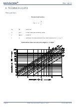
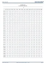
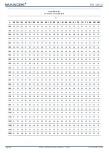
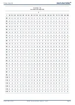
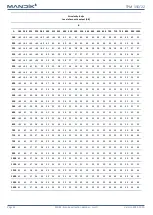
Page 46: ...CHNICAL DATA Pressure loss Pressure loss calculation Determination of pressure loss by using diagram 1 2 kg m3 p w2 2 p Pa presure loss w m s air flow speed in nominal damper section kg m3 air density...

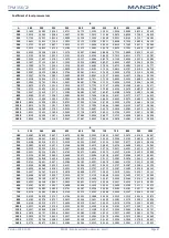
Page 47: ...9 1 4348 1 1611 0 9418 0 7684 0 6936 0 6477 0 5712 0 4998 0 4454 0 4046 1600 1 8054 1 4280 1 1169 0 9367 0 7667 0 6902 0 6443 0 5678 0 4981 0 4420 0 4029 B A 550 560 600 630 650 700 710 750 800 900 10...

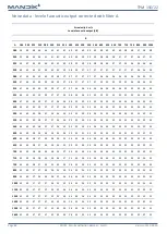
Page 48: ...9 38 37 36 36 36 35 35 35 34 34 33 33 34 34 34 33 33 33 33 550 44 40 40 38 37 37 36 36 35 35 34 34 34 34 34 33 33 33 33 33 33 33 560 44 40 40 38 37 37 36 35 35 35 34 34 34 34 34 34 33 33 33 33 33 33 6...

Page 49: ...0 40 40 40 40 40 39 39 39 39 550 49 47 46 44 43 43 42 41 40 40 40 40 40 40 40 39 39 39 39 39 39 38 560 49 47 46 44 43 43 42 41 40 40 40 40 40 40 40 39 39 39 39 39 39 38 600 50 47 45 43 43 42 42 41 40...

Page 50: ...5 45 45 45 45 45 45 45 43 43 550 55 53 50 50 48 47 45 45 45 45 45 45 45 45 45 45 45 45 45 44 44 44 560 55 53 50 50 48 47 45 45 45 45 45 45 45 45 45 45 45 45 45 44 44 44 600 55 53 50 50 48 47 45 45 45...

Page 51: ...8 48 48 48 48 48 48 48 48 48 550 60 58 55 54 53 52 52 50 50 48 48 48 48 48 48 48 48 48 48 48 48 48 560 60 58 55 54 53 52 52 50 50 48 48 48 48 48 48 48 48 48 48 48 48 48 600 60 58 55 54 52 52 51 50 49...

Page 52: ...3 53 53 53 53 53 53 52 51 51 550 63 62 59 58 56 56 55 55 54 53 53 53 53 53 53 53 53 53 52 52 51 51 560 63 62 59 58 56 56 55 55 54 53 53 53 53 53 53 53 53 53 52 52 51 51 600 63 62 59 58 56 55 55 54 54...

Page 53: ...7 57 56 56 56 56 56 56 55 55 550 65 65 62 62 60 60 58 57 58 58 57 57 57 56 56 56 56 56 56 56 55 55 560 65 65 62 62 60 60 58 57 58 58 57 57 57 56 56 56 56 56 56 56 55 55 600 65 65 62 62 60 59 58 58 58...

Page 54: ...s holders including pins metal parts of blade Inspection hole cover and fasteners if they are parts of the cover The leaf of the damper is made from three Promatect H sheets thickness 20 mm connected...

Page 55: ...rice of damper For unloading and further manipulation with the damper is necessary to use appropriate tooling forklifts due to damper weight Dampers are fragile Dampers are transported by box freight...

Page 56: ...connector block the protection box is made of calcium silicate plates Procedure Use drill drill size acc To suit connecting cable 2 mm for seal up by mastic and make two holes It is possible to drill...

Page 57: ...ill size acc to suit connecting cable 2 mm for seal up by mastic and make holes min pitch of the holes must be 30 mm number of holes depends on the type of control module It is possible to drill holes...

Page 58: ...another appropriate way Results of regular checks imperfections found and all important facts connected with the damper function must be recorded in the FIRE BOOK and immediately repor ted to the oper...

Page 59: ...sm BEN BEE BE InMax 50 75 S for 24V 54 with actuating mechanism BEN BEE SR for 24V 65 Design 65 is not available by using actuating mechanism BE InMax 50 75 S WEIGHT kg Dob sk 550 267 24 Hostomice Cze...

Page 60: ...ual product information see www mandik co uk MAND K a s Dob sk 550 267 24 Hostomice Czech Republic Tel 420 311 706 742 E Mail mandik mandik cz Manufacturer MANDIK UK Ltd 130 Aztec West Bristol BS32 4U...

Reviews: