background image

5

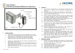
The damper must be installed so that the damper leaf (in a closed position) is placed on the edge
with the fire dividing structure or in the fire dividing structure - marked on the damper with the sticker
"EDGE OF THE WALL" (Fig. 1 and 2). If this solution is not possible, the duct between the fire
dividing  structure  and  the  damper  must  be  min.  to  the  edge  of  the  wall  protected  (Fig.  3)  as
specified in the standard EN 73 0872. The design must be in accordance with the relevant TPM for
the given type of damper.

Until  the  wall  is  plastered  it  is  necessary  to  protect  the  control  mechanism  from  damage  and
contamination  by  covering  it.  The  damper  body  must  not  be  deformed  during  walling.  After
installing the damper, the damper leaf must not scrub on the damper body when opening or closing.

Fire damper

Damper blade

Fire dividing
construction

Fire damper

Damper blade

Fire dividing
construction

Protected duct

Fire damper

Damper blade

Fire dividing
construction


The fire damper can be built into a rigid wall structure made of e.g. ordinary concrete/masonry,
aerated concrete with min. 100mm thickness or into a rigid ceiling structure made of e.g. ordinary
concrete, aerated concrete with min. 110mm thick. Construction openings and penetrations must
be made in accordance with the relevant TPM for the given type of damper.


The fire damper can be built into a light plasterboard wall construction with a min.100 mm thickness.


The fire damper can be installed outside the wall construction. The ducting and the part of the
damper between the wall structure and the damper leaf (marked with the WALL EDGE sticker on
the damper) must be protected by fire insulation. The insulation and penetration must be made in
accordance with the relevant TPM for the damper type.

Summary of Contents for FDMR

Page 1: ......

Page 2: ...cription 3 2 Design 3 3 Placement and Assembly 4 4 Dimensions 6 5 Electrical elements wiring diagram 11 6 Material surface protection 12 7 Product data 12 8 Logistic terms 12 9 Warranty 12 10 Installa...

Page 3: ...designed for environments protected against weather conditions with climatic conditions in 3K5 class with temperature limitation 20 C to 50 C without condensation icing ice formation without water an...

Page 4: ...damper using the button on the temperature sensor simulates fuse failure Using a special key supplied with the actuator the damper leaf can be manually adjusted to any position and the position secure...

Page 5: ...closing Fire damper Damper blade Fire dividing construction Fire damper Damper blade Fire dividing construction Protected duct Fire damper Damper blade Fire dividing construction The fire damper can b...

Page 6: ...ExPro TT 2 Body 2 damper 9 Inspection hole covering 3 Damper blade 10 Control lever 4 Electrical actuator Schischek ExMax 15BF 11 Pin with lever 5 Mechanical actuator Atex 12 Initiation button 6 Therm...

Page 7: ...ExPro TT 2 Body 2 damper 9 Inspection hole covering 3 Damper blade 10 Control lever 4 Electrical actuator Schischek ExMax 15BF 11 Pin with lever 5 Mechanical actuator Atex 12 Initiation button 6 Therm...

Page 8: ...Thermo electrical fuse ExPro TT 2 Damper blade 8 Inspection hole covering 3 Electrical actuator Schischek ExMax 15BF 9 Control lever 4 Mechanical actuator Atex 10 Pin with lever 5 Thermal fuse 11 Ini...

Page 9: ...Thermo electrical fuse ExPro TT 2 Damper blade 8 Inspection hole covering 3 Electrical actuator Schischek ExMax 15BF 9 Control lever 4 Mechanical actuator Atex 10 Pin with lever 5 Thermal fuse 11 Ini...

Page 10: ...side length 1000 mm FDMQ from 150x150 to 1500x800 FDMR from 100 to 800 mm FDMA PM 900 and 1000 Square damper flanges with a width of 30 mm are provided with oval holes in the corners The connection di...

Page 11: ...e 21 a 22 Adjustment time drive reverse gear 30 s 10 s Ambient operating temperature Storage temperature 40 C 40 C at T6 40 C 50 C at T5 40 C 70 C Humidity 0 95 rH non condensing Connection optional a...

Page 12: ...box freight vehicles no sharp shocks must occur and the ambient temperature must not exceed 40 C For handling during transport the dampers must be protected against mechanical damages and weather imp...

Page 13: ...the AUTHORISED PERSON themselves directly with the trainer Upon the expiry of the validity of the CERTIFICATE it loses its validity and is excluded from the trainer s registration Only professionals...

Page 14: ...reserves the right for innovations of the product For actual product information see www mandik com MAND K a s Dob sk 550 26724 Hostomice Czech Republic Tel 420 311 706 706 E Mail mandik mandik cz ww...

Reviews: