


3
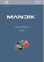
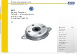
Fire dampers are closures in the ducts of air-conditioning units, which prevent the spread of fire
and combustion products from one fire section to another by closing the air ducts in the places of
installation according to EN 73 0872.
The damper leaf automatically closes the air passage by means of the closing the mechanism's
spring or the actuator's return spring.
The impulse to release the lowering lever can be manual (pressing the lowering button on the
mechanism) or thermal (pressing the thermal fuse).
The actuator return spring is activated when the ExPro-TT temperature sensor is activated
(pressing the reset button on the sensor or temperature activation) or the actuator power supply
is interrupted.
After closing the leaf, the damper is sealed against the passage of smoke with a silicone seal.
At the same time, the damper leaf is embedded in the mass, which increases its volume due to
the increasing temperature and closes the air duct airtight.
Damper fire resistance tests were performed according to the test standard EN 1366-2 and
harmonised product standards EN 15650. The classification was performed according to the
standard EN 13501-3+A1. Fire resistance depends on the installation method on the construction
site. The installation must be in accordance with the latest current version of the relevant TPMs.
The dampers are designed for environments protected against weather conditions with climatic
conditions in 3K5 class with temperature limitation -20°C to +50°C, without condensation, icing,
ice formation, without water and sources other than rain according to EN 60721-3-3 zmA2 and
environment with danger of explosion of group and category 2G Ex h IIC T6… T3 Gb according
to EN ISO 80079-36. If the damper is equipped with electrical elements, the temperature range is
narrowed according to the temperature range of the electrical elements used. The non-explosive
group of a damper with electrical elements depends on the non-explosive design of the installed
electrical elements on the damper. Electrical equipment installed together with the damper must
be of a design corresponding to the given zone. When determining spaces, the principle is that it
does not matter whether the specified environment is outside or inside the damper.
≥ 72°C
68°C
T6
≥ 104°C
98°C
T5
≥ 147°C
140°C
T3
Fire dampers are designed for air without abrasive, chemical and sticky additives.
(mechanical control) with thermal fuse, which activates the closing
device within 120 seconds at the latest when the nominal starting temperature of 72°C is reached.
Up to a temperature of 70°C, the closing device will not self-start. If other start temperatures are
required, thermal fuses with a nominal start temperature of + 104°C or + 147°C can be supplied
(must be specified in the order).
according to paragraph 2.1. can be supplemented by signal-
ling the damper leaf position "CLOSED" or "OPEN" with a limit switch.
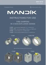
Summary of Contents for FDMR
Page 1: ......