12
Condensate Drain
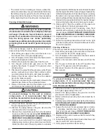
Figure 6. Condensate Drain Location
Figure 5. Roof Top Installation
Figure 4. Ground Level Installation
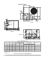
Unit Size
Internal Filter Size
R6GD-X36
(2) 16” x 25” x 1”
or
(2) 16” x 25” x 2”
R6GD-X48 / X60
(2) 18” x 25” x 1”
or
(2) 18” x 25” x 2”
Table 2. Internal Filter Sizes
Removal of Internal Filter Rack (3 Phase Only)
1. Remove the return air panel from the unit.
2. Remove the height adjustment screw from the inside
of the rack.
3. Remove (1) screw securing the assembly to the coil
located on the left leg of the rack. NOTE: The assembly
can now be easily collapsed and removed from the unit.
See Figure 7 for fi lter rack securing screw locations.
Securing
Screws
Figure 7. Internal Filter Rack Location
Installing Filters in the Filter Rack (3 Phase Only)
1. Remove access panel screws from return air panel.
(Hint: Loosen the unit’s top panel screws near the
top edge of the access panel. The access panel was
designed to be captured underneath the top panel.)
2. Slide the fi rst fi lter between both guide channels of
fi lter rack and allow the fi lter to drop easily into place.
3. Verify the bottom of the fi lter is within the channels of
the rack.
4. Slide the 2nd fi lter between both guide channels of
fi lter rack.
5. Verify the bottom of the fi lter is within the channels of
the rack.
6. Replace access cover by sliding the top edge of panel
under the lip of the unit’s top panel. Secure access
panel by replacing the screws.
Removing Filters from Filter Rack (3 Phase Only)
1. Remove access panel screws from return air panel.
(Hint: Loosen the unit’s top panel screws near the
top edge of the access panel. The access panel was
designed to be captured underneath the top panel.)
2. Remove upper fi lter by gently pulling fi lter through the
access panel opening.
3. Remove lower fi lter by lifting media to top of fi lter rack.
Remove in the same manner as described in step 2.
4. Install new fi lter in the fi lter rack as described in the
previous section.


