background image

HydroBank MS Installation and Operation Manual MAMM-WSHP-IOM-1MSA (October 2014) 

29

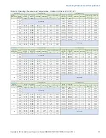
Operating Pressures and Temperatures

Table 10: Operating Pressures and Temperatures - Horizontal Unit Sizes 030, 036, 042

Entering 

Water Temp 

°F

Water 

Flow GPM

Suction 

Pressure 

PSIG

Discharge 

Pressure 

PSIG

Superheat

Subcooling

Water Temp 

Rise °F

Air DB Drop 

°F

Suction 

Pressure 

PSIG

Discharge 

Pressure 

PSIG

Superheat

Subcooling

Water Temp 

Rise °F

Air DB Drop 

°F

4.9

66-76

265-285

9-14

1-6

6-8

17-23

7.0

67-77

268-288

9-14

1-6

4-6

17-23

8.4

69-79

271-291

10-15

1-6

3-5

17-23

4.9

120-130

176-196

11-16

5-10

17-19

21-27

82-92

286-306

10-15

1-6

7-9

20-26

7.0

120-130

167-187

11-16

4-9

12-14

21-27

83-93

289-309

11-16

1-6

5-7

20-26

8.4

120-130

163-183

11-16

4-9

10-12

21-27

85-95

292-312

11-16

1-6

4-6

21-27

4.9

126-136

236-256

6-11

6-11

17-19

20-26

115-125

312-332

11-16

1-6

10-12

26-32

7.0

126-136

225-245

6-11

5-10

12-14

20-26

117-127

316-336

11-16

1-6

7-9

26-32

8.4

126-136

220-240

6-11

4-9

10-12

20-26

120-130

319-339

12-17

1-6

6-8

26-32

4.9

134-144

314-334

5-10

6-11

16-18

19-25

148-158

346-366

15-20

1-6

11-13

31-37

7.0

134-144

298-318

5-10

5-10

11-13

19-25

151-161

350-370

15-20

1-6

8-10

31-37

8.4

134-144

292-312

5-10

4-9

9-11

19-25

154-164

353-373

17-22

1-6

6-8

32-38

4.9

139-149

416-436

5-10

7-12

15-17

17-23

7.0

139-149

395-415

5-10

6-11

10-12

17-23

8.4

139-149

387-407

5-10

5-10

8-10

17-23

Entering 

Water Temp 

°F

Water 

Flow GPM

Suction 

Pressure 

PSIG

Discharge 

Pressure 

PSIG

Superheat

Subcooling

Water Temp 

Rise °F

Air DB Drop 

°F

Suction 

Pressure 

PSIG

Discharge 

Pressure 

PSIG

Superheat

Subcooling

Water Temp 

Rise °F

Air DB Drop 

°F

6.3

67-77

264-284

11-16

3-8

6-8

17-23

9.0

69-79

266-286

11-16

3-8

4-6

18-24

10.8

70-80

269-289

12-17

3-8

3-5

18-24

6.3

122-132

175-195

9-14

4-9

16-18

21-27

83-93

284-304

12-17

3-8

7-9

20-26

9.0

122-132

166-186

9-14

3-8

11-13

21-27

85-95

287-307

13-18

3-8

5-7

21-27

10.8

122-132

163-183

9-14

3-8

9-11

21-27

87-97

290-310

14-19

3-8

4-6

21-27

6.3

128-138

236-256

5-10

5-10

15-17

21-27

117-127

310-330

13-18

3-8

9-11

26-32

9.0

128-138

224-244

5-10

4-9

11-13

21-27

120-130

314-334

14-19

3-8

6-8

27-33

10.8

128-138

219-239

5-10

3-8

9-11

21-27

122-132

317-337

15-20

3-8

5-7

27-33

6.3

137-147

313-333

4-9

5-10

14-16

19-25

151-161

344-364

18-23

3-8

10-12

31-37

9.0

137-147

297-317

4-9

4-9

10-12

19-25

154-164

347-367

19-24

3-8

7-9

32-38

10.8

137-147

291-311

4-9

4-9

8-10

19-25

157-167

351-371

20-25

3-8

6-8

33-39

6.3

141-151

414-434

4-9

6-11

13-15

18-24

9.0

141-151

394-414

4-9

5-10

9-11

18-24

10.8

141-151

386-406

4-9

4-9

8-10

18-24

Entering 

Water Temp 

°F

Water 

Flow GPM

Suction 

Pressure 

PSIG

Discharge 

Pressure 

PSIG

Superheat

Subcooling

Water Temp 

Rise °F

Air DB Drop 

°F

Suction 

Pressure 

PSIG

Discharge 

Pressure 

PSIG

Superheat

Subcooling

Water Temp 

Rise °F

Air DB Drop 

°F

7.4

68-78

271-291

6-11

1-6

6-8

18-24

10.5

70-80

274-294

6-11

1-6

4-6

18-24

12.6

71-81

277-297

7-12

1-6

3-5

18-24

7.4

120-130

176-196

11-16

9-14

16-18

21-27

85-95

292-312

7-12

1-6

7-9

21-27

10.5

120-130

167-187

11-16

7-12

11-13

21-27

87-97

295-315

7-12

1-6

5-7

21-27

12.6

120-130

164-184

11-16

7-12

9-11

21-27

89-99

298-318

8-13

1-6

4-6

22-28

7.4

126-136

237-257

6-11

10-15

15-17

21-27

119-129

319-339

7-12

1-6

9-11

27-33

10.5

126-136

225-245

6-11

8-13

10-12

21-27

122-132

323-343

8-13

1-6

7-9

27-33

12.6

126-136

221-241

6-11

8-13

9-11

21-27

124-134

326-346

9-14

1-6

5-7

28-34

7.4

135-145

315-335

5-10

11-16

14-16

19-25

154-164

354-374

10-15

1-6

11-13

32-38

10.5

135-145

299-319

5-10

9-14

10-12

19-25

157-167

357-377

11-16

1-6

8-10

32-38

12.6

135-145

293-313

5-10

8-13

8-10

19-25

160-170

361-381

12-17

1-6

6-8

33-39

7.4

139-149

417-437

5-10

12-17

13-15

18-24

10.5

139-149

397-417

5-10

10-15

9-11

18-24

12.6

139-149

389-409

5-10

9-14

8-10

18-24

Horizontal 030

Full Load Cooling

Full Load Heating

30

Out of Range

40

60

80

Horizontal 042

Full Load Cooling

Full Load Heating

Out of Range

Horizontal 036

Full Load Cooling

Full Load Heating

30

Out of Range

100

40

60

80

100

Out of Range

30

Out of Range

40

60

80

Out of Range

100

Summary of Contents for HydroBank MS

Page 1: ...MAMM WSHP IOM 1MSA October 2014 PN 7144926 HydroBank MS Compact Single Stage Water Source Heat Pumps to 6 Tons Horizontal and Vertical Installation operation and maintenance manual ...

Page 2: ...l 13 Ventilation Air Considerations 14 Electrical Connections 14 Hot Gas Bypass Option 15 Hot Gas Reheat Option 15 Motorized Shutoff Valve Option 16 HP 5 Microprocessor Control 16 Thermostat Wiring 19 EPiC DDC Controls 22 Cleaning and Flushing the Water System 23 Startup 24 General Maintenance 25 Troubleshooting 26 Physical Data and Operating Limits 27 Operating Pressures and Temperatures 28 Elect...

Page 3: ... of this machine depend upon the strict observance of these precautions Read this manual thoroughly before operating or servic ing this unit WARNING Indicates a potentially hazard ous situation which if not avoided could result in death or serious injury CAUTION Indicates a potentially hazardous situation which if not avoided could result in minor or moderate injury It could also be used to alert ...

Page 4: ... 12 000 042 42 000 Y None standard 015 15 000 048 48 000 X Special 019 19 000 060 60 000 024 24 000 070 70 000 Digit 14 Heat Exchanger 030 30 000 C Copper standard N Cupro Nickel Digit 8 Voltage A 115 60 1 F 208 230 60 3 Digit 13 Blower Motor D 208 230 60 1 G 460 60 3 A PSC standard E 265 277 60 1 C ECM Constant Torque E ECM Constant CFM Digit 9 Return Air L Left Digit 10 Discharge Air Digit 12 Ap...

Page 5: ...ondensate Pan C Compressor Blanket S Galvanized Steel Y None standard T Stainless Steel Digit 28 29 Cabinet Insulation Digit 41 Switching Devices 01 Standard 1 2 Dual Density Fiberglass A Unit Disconnect Switch 02 1 2 Closed Cell Foam IAQ B Water Differential Pressure Switch DPS XX Special C Dirty Filter Switch D Combo Disconnect Dirty Filter Switch Digits 30 32 Refrigerant Circuit Options E Combo...

Page 6: ...eteriorate certain plastic mate rials and cause permanent damage Keep units upright IMPORTANT Operating a unit after it has been stored or transported on its side can result in seri ous compressor damage which is not covered under the equipment warranty Make sure the unit is first returned to its normal upright position for at least 24 hours before operating Unit Protection Keep units covered duri...

Page 7: ...ase depending on factors such as electrical installation codes If return air is not ducted be sure to provide enough clearance for adequate airflow Figure 1 Suggested Horizontal Unit Clearances 2 ft 61 cm service access filter removal width of filter 2 ft 61 cm motor access end discharge 2 ft 61 cm motor access straight discharge Mounting Horizontal units are typically suspended from the ceiling u...

Page 8: ...the electrical wiring from the motor 13 Slide the blower housing and motor assembly verti cally upward and out of the unit 14 Rotate the assembly 180 degrees and turn it 90 degrees as shown in Figure 4 15 Slide the assembly into the slot from which you removed the access panel 16 Verify that in its new configuration the orifice ring on the blower motor faces the access opening on the side or end o...

Page 9: ... Figure 6 below and Discharge Duct Sizing Considerations on page 12 Good design practice requires a flexible connector between the collar and transition to the main duct sys tem This connector attenuates sound from the unit especially fan sound and simplifies unit removal Ductwork should be lined with an acoustic thermal insu lation that is a minimum of inch thick For sensitive installations use 1...

Page 10: ...c unit may increase or be reduced depending on several factors such as maintenance requirements and mechanical or electrical installation codes Figure 7 Suggested Vertical Unit Clearances 2 ft 61 cm service access 1 ft 31 cm non ducted units for even air distribution across coil filter removal width of filter Piping Heat pumps are typically connected to supply and return piping in a two pipe rever...

Page 11: ...or heat pumps in the cooling mode Condensate Drain Piping Condensate lines on vertical units are internally trapped A flush mounted condensate drain connection is pro vided on the outside of the cabinet Condensate piping can be PVC steel or copper PVC typically eliminates the need to insulate the pipe to prevent sweating Do not locate any point in the drain system above the drain connection of any...

Page 12: ...eater than 7 for diverging elements Suggested discharge ductwork sizing for HydroBank units based on these recommendations is provided in Table 1 and Table 2 to the right All Mammoth units are tested for airflow as part of our ISO ARI certification program It is possible to have airflow that is above or below design requirements for many reasons The first step in evaluating and correct ing air flo...

Page 13: ...n cause severe injury or death Lock and tag out all electric power during installation Wiring to the unit is routed through the electrical knock outs in the front corner of the unit See Figure 12 and Figure 13 For detailed information on knockout loca tions and sizes see the dimensional drawings provided with your unit submittal package Figure 12 Horizontal Unit Electrical Connections Field contro...

Page 14: ...ooling the 3 way diverting valve opens for economizer cooling if the entering water temperature is below the set point of the aquastat If it is above the aquastat set point the compressor is automatically ener gized for mechanical cooling Control Sequence with Two Stage Thermostat On a call from the thermostat for stage one cooling the 3 way diverting valve opens for economizer cooling if the ente...

Page 15: ...help stabi lize the system balance point This option includes a hot gas bypass valve Hot Gas Reheat Option Hot gas reheat coil Hot gas reheat valve Hot gas reheat is the ideal solution to prevent over cooling of the occupied space when the unit is in dehu midification mode Hot gas is used to reheat saturated air coming off the cooling coil without using an external heat source NOTE This option req...

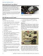
Page 16: ...ly energize the fan whenever the compressor is on Board operable on 50 and 60 cycle power Emergency shutdown from a field supplied signal Unoccupied night setback and night setup mode from a field supplied signal Dry contact alarm signal for connection of a fault signal to a DDC controller Auxiliary dry contact for tie in of a motorized valve when the compressor is on or optional compressor status...

Page 17: ...of low pressure bypass has been satisfied Optional Freezestat Switch If the leaving fluid tem perature falls to 32 F the freezestat switch opens After 10 seconds the unit goes into lockout mode Condensate Overflow Protection If the drain pan sensor comes in contact with moisture for more than 30 seconds the unit goes into lockout mode LED STATUS ON Normal operating mode 1 Flash High pressure fault...

Page 18: ...alve when the compressor is on TEST PIN JUMPER An on board pair of male termi nals provides for an optional mode of operation which defeats both forms of compressor time delays If a hard wired jumper is placed across the TEST and TEST IN terminals the random start time delay and the compressor s five minutes of anti short cycle time delay will be ignored However the two four and six second time de...

Page 19: ...iring from the thermostat is rout ed through an electrical knockout in the front of the unit See Figure 12 and Figure 13 on page 13 A remov able terminal block simplifies hookup See Figure 20 To remove it gently pull it straight out from the control board Thermostat connections are made as described in the following diagrams Figure 20 HP 5 Controller Fixed 8 Pole Terminal Block P2 Removable 8 Pole...

Page 20: ... MS Installation and Operation Manual MAMM WSHP IOM 1MSA October 2014 Thermostat Wiring Figure 22 Thermostat Wiring With Override and Night Setback Figure 23 Thermostat Wiring Emergency Shutdown Mode With Override ...

Page 21: ...HydroBank MS Installation and Operation Manual MAMM WSHP IOM 1MSA October 2014 21 Thermostat Wiring Figure 24 Thermostat Wiring Emergency Shutdown Mode Without Override ...

Page 22: ...Appli cation Controller B ACC Standard Device Profile as defined in ANSI ASHRAE Standard 135 2012 BACnet Annex L Protocol Revision 9 EPiC controllers are also capable of BMS network com munication using LonWorks LonTalk protocol with an optional LonCard to only include the required neuron chip There are no requirements for LonCard programming A sensor HMI network port allows 5 remote mounted wall ...

Page 23: ... and blow down making sure domestic water fill valves are set to make up water at the same rate 9 Check the pressure gauge at the pump suction and manually adjust the makeup to hold the same posi tive steady pressure both before and after opening the drain valves 10 Flush the system for at least two hours or longer if required until the drain water is clear and clean 11 Shut off the supplemental h...

Page 24: ...inst short cycling In the cooling mode after a few minutes of operation check the discharge grilles for cool air delivery 5 Measure the temperature difference between enter ing and leaving water It should be approximately 1 times greater than the heating mode tempera ture difference see Step 6 6 In the heating mode measure the temperature dif ference between entering and leaving air and enter ing ...

Page 25: ...ndensate drain and drain pan should be checked on an annual basis to verify positive drainage and cleaned or flushed as necessary Electrical Check the tightness of all electrical terminals twice each year Retighten as needed WARNING Loose electrical terminals can lead to erratic unit operation and arcing which may cause fires WARNING Electric shock and moving equipment hazard Can cause severe inju...

Page 26: ...s If significantly different check for duct leaks Unit doesn t operate in cooling X X Low refrigerant charge Recover refrigerant and re charge to nameplate X X Restricted metering device Check superheat and subcooling Replace metering device X Defective reversing valve Perform reversing valve touch test X X Thermostat improperly located Check thermostat location and for air drafts behind thermosta...

Page 27: ...8 060 070 Compressor Type Qty 1 Rotary Reciprocating Scroll Max Water Working Pressure 400 PSIG 2758 kPa Blower Motor Type Speeds PSC 3 PSC 3 or ECM 5 PSC Motor HP Consult Factory 1 5 1 5 1 3 1 3 1 2 1 2 1 2 1 2 3 4 3 4 ECM Motor HP NA 1 3 1 3 1 3 1 2 1 2 1 2 1 2 3 4 1 1 Blower Wheel Size Dia x W Consult Factory 9 x 6 9 x 6 9 x 7 10 x 7 10 x 7 10 x 8 10 x 7 10 x 7 10 x 10 10 x 10 Water Connection ...

Page 28: ... 333 6 11 5 10 6 8 23 29 5 4 119 129 164 184 10 15 10 15 10 12 22 28 92 102 316 336 7 12 5 10 5 7 24 30 3 2 125 135 237 257 5 10 14 19 17 19 22 28 124 134 339 359 6 11 6 11 11 13 30 36 4 5 125 135 225 245 5 10 12 17 12 14 22 28 127 137 342 362 7 12 5 10 8 10 30 36 5 4 125 135 221 241 5 10 11 16 10 12 22 28 130 140 346 366 7 12 5 10 6 8 31 37 3 2 133 143 315 335 4 9 15 20 16 18 20 26 160 170 375 39...

Page 29: ... 14 3 8 9 11 21 27 87 97 290 310 14 19 3 8 4 6 21 27 6 3 128 138 236 256 5 10 5 10 15 17 21 27 117 127 310 330 13 18 3 8 9 11 26 32 9 0 128 138 224 244 5 10 4 9 11 13 21 27 120 130 314 334 14 19 3 8 6 8 27 33 10 8 128 138 219 239 5 10 3 8 9 11 21 27 122 132 317 337 15 20 3 8 5 7 27 33 6 3 137 147 313 333 4 9 5 10 14 16 19 25 151 161 344 364 18 23 3 8 10 12 31 37 9 0 137 147 297 317 4 9 4 9 10 12 1...

Page 30: ...2 28 88 98 313 333 8 13 3 8 4 6 24 30 10 5 124 134 241 261 7 12 9 14 15 17 21 27 118 128 336 356 8 13 3 8 9 11 29 35 15 0 124 134 229 249 7 12 8 13 11 13 21 27 121 131 339 359 8 13 3 8 7 9 30 36 18 0 124 134 224 244 7 12 7 12 9 11 21 27 123 133 343 363 9 14 3 8 6 8 30 36 10 5 132 142 320 340 5 10 10 15 14 16 20 26 153 163 372 392 11 16 3 8 11 13 35 41 15 0 132 142 304 324 5 10 8 13 10 12 20 26 156...

Page 31: ...7 12 6 8 24 30 5 4 119 129 165 185 11 16 10 15 10 12 22 28 94 104 319 339 6 11 7 12 5 7 25 31 3 2 125 135 238 258 6 11 15 20 17 19 22 28 127 137 341 361 6 11 7 12 11 13 31 37 4 5 125 135 226 246 6 11 12 17 12 14 22 28 129 139 345 365 6 11 7 12 8 10 31 37 5 4 125 135 222 242 6 11 11 16 10 12 22 28 132 142 349 369 7 12 7 12 6 8 32 38 3 2 134 144 316 336 4 9 15 20 16 18 20 26 163 173 378 398 8 13 7 1...

Page 32: ... 16 5 10 9 11 22 28 82 92 280 300 14 19 2 7 4 6 20 26 6 3 129 139 233 253 6 11 8 13 15 17 21 27 110 120 300 320 13 18 2 7 8 10 25 31 9 0 129 139 221 241 6 11 7 12 11 13 21 27 113 123 303 323 14 19 2 7 6 8 25 31 10 8 129 139 217 237 6 11 6 11 9 11 21 27 115 125 306 326 15 20 2 7 5 7 26 32 6 3 137 147 309 329 4 9 8 13 14 16 20 26 142 152 332 352 18 23 2 7 10 12 30 36 9 0 137 147 294 314 4 9 7 12 10 ...

Page 33: ... 12 9 11 22 28 87 97 310 330 10 15 1 6 4 6 23 29 10 5 124 134 242 262 8 13 10 15 15 17 21 27 117 127 332 352 9 14 1 6 9 11 29 35 15 0 124 134 230 250 8 13 8 13 11 13 21 27 120 130 336 356 10 15 1 6 7 9 29 35 18 0 124 134 225 245 8 13 8 13 9 11 21 27 122 132 339 359 10 15 1 6 5 7 30 36 10 5 132 142 321 341 6 11 11 16 14 16 20 26 151 161 368 388 12 17 1 6 11 13 34 40 15 0 132 142 305 325 6 11 9 14 1...

Page 34: ...1 12 9 15 20 E 265 277 1 60 8 5 46 3 1 1 3 11 6 13 7 15 20 G 460 60 3 3 6 30 1 3 1 3 4 9 5 8 15 20 D 208 230 1 60 14 4 74 5 6 1 2 20 0 23 6 25 35 F 208 230 3 60 9 1 70 5 6 1 2 14 7 17 0 20 25 E 265 277 1 60 10 5 67 3 5 1 2 14 0 16 6 20 25 G 460 60 3 3 9 34 1 9 1 2 5 8 6 8 15 20 D 208 230 1 60 15 0 88 5 6 1 2 20 6 24 4 25 35 F 208 230 3 60 10 1 68 5 6 1 2 15 7 18 2 20 25 G 460 3 60 4 4 34 3 5 1 2 7...

Page 35: ... 35 F 208 230 3 60 9 1 70 3 5 1 2 12 6 14 9 15 20 E 265 277 1 60 10 5 67 3 2 1 2 13 7 16 3 20 25 G 460 60 3 3 9 34 2 1 1 2 6 0 7 0 15 20 D 208 230 1 60 15 0 88 3 5 1 2 18 5 22 3 25 35 F 208 230 3 60 10 1 68 3 5 1 2 13 6 16 1 20 25 G 460 60 3 4 4 34 2 1 1 2 6 5 7 6 15 20 D 208 230 1 60 17 4 84 5 0 1 22 4 26 8 30 40 F 208 230 3 60 10 9 88 5 0 1 15 9 18 6 20 25 G 460 60 3 5 3 44 4 6 3 4 9 9 11 2 15 2...

Page 36: ... 3 11 6 13 7 15 20 G 460 60 3 3 6 30 1 3 1 3 4 9 5 8 15 20 D 208 230 1 60 14 4 74 5 6 1 2 20 0 23 6 25 35 F 208 230 3 60 9 1 70 5 6 1 2 14 7 17 0 20 25 E 265 277 1 60 10 5 67 3 5 1 2 14 0 16 6 20 25 G 460 60 3 3 9 34 1 9 1 2 5 8 6 8 15 20 D 208 230 1 60 F 208 230 3 60 G 460 3 60 D 208 230 1 60 15 0 88 5 6 1 2 20 6 24 4 25 35 F 208 230 3 60 10 1 68 5 6 1 2 15 7 18 2 20 25 G 460 3 60 4 4 34 3 5 1 2 ...

Page 37: ... 12 6 14 9 15 20 E 265 277 1 60 10 5 67 3 2 1 2 13 7 16 3 20 25 G 460 60 3 3 9 34 2 1 1 2 6 0 7 0 15 20 D 208 230 1 60 F 208 230 3 60 G 460 3 60 D 208 230 1 60 15 0 88 3 5 1 2 18 5 22 3 25 35 F 208 230 3 60 10 1 68 3 5 1 2 13 6 16 1 20 25 G 460 60 3 4 4 34 2 1 1 2 6 5 7 6 15 20 D 208 230 1 60 17 4 84 5 0 1 22 4 26 8 30 40 F 208 230 3 60 10 9 88 5 0 1 15 9 18 6 20 25 G 460 60 3 5 3 44 4 6 3 4 9 9 1...

Page 38: ...58 1 524 1 479 1 429 1 379 1 328 1 265 Lo 1 288 1 282 1 265 1 249 1 218 1 187 1 154 1 112 1 069 1 026 Med 1 536 1 533 1 519 1 506 1 488 1 466 1 443 1 416 1 387 1 357 1 311 1 266 1 220 1 162 Hi 1 750 1 723 1 693 1 663 1 632 1 598 1 564 1 531 1 487 1 437 1 386 1 335 1 272 1 202 Lo 1 289 1 288 1 273 1 255 1 227 1 191 1 153 1 102 1 051 1 000 Med 1 538 1 535 1 528 1 514 1 499 1 475 1 449 1 420 1 387 1 ...

Page 39: ... 4 1 328 1 314 1 303 1 292 1 278 1 263 1 250 1 236 1 226 1 208 1 195 1 183 1 171 1 156 1 139 1 125 1 110 1 092 5 1 488 1 477 1 465 1 452 1 443 1 429 1 416 1 400 1 386 1 375 1 365 1 352 1 338 1 313 1 289 1 264 1 236 1 763 743 719 699 674 647 622 589 570 558 542 2 1 035 1 018 1 002 987 971 954 936 917 898 883 865 844 813 3 1 171 1 155 1 139 1 125 1 111 1 096 1 080 1 063 1 048 1 033 1 018 998 984 968...

Page 40: ...40 HydroBank MS Installation and Operation Manual MAMM WSHP IOM 1MSA October 2014 Typical Wiring Diagrams Typical Wiring Diagrams Wiring Diagram PSC Motor Single Phase 208 230 or 277V 1PH 60H ...

Page 41: ...HydroBank MS Installation and Operation Manual MAMM WSHP IOM 1MSA October 2014 41 Typical Wiring Diagrams Wiring Diagram PSC Motor Three Phase 208 230 or 460V 3PH 60H ...

Page 42: ...42 HydroBank MS Installation and Operation Manual MAMM WSHP IOM 1MSA October 2014 Typical Wiring Diagrams Wiring Diagram Constant Torque ECM Motor Single Phase 208 230V 1PH 60H ...

Page 43: ...HydroBank MS Installation and Operation Manual MAMM WSHP IOM 1MSA October 2014 43 Typical Wiring Diagrams Wiring Diagram Constant Torque ECM Motor Single Phase 277V 1PH 60H ...

Page 44: ...44 HydroBank MS Installation and Operation Manual MAMM WSHP IOM 1MSA October 2014 Typical Wiring Diagrams Wiring Diagram Constant Torque ECM Motor Three Phase 208 230V 1PH 60H ...

Page 45: ...HydroBank MS Installation and Operation Manual MAMM WSHP IOM 1MSA October 2014 45 Typical Wiring Diagrams Wiring Diagram Constant Torque ECM Motor Three Phase 460V 1PH 60H ...

Page 46: ...46 HydroBank MS Installation and Operation Manual MAMM WSHP IOM 1MSA October 2014 Typical Wiring Diagrams Wiring Wiring Diagram EPiC DDC 560 Controller ...

Page 47: ...HydroBank MS Installation and Operation Manual MAMM WSHP IOM 1MSA October 2014 47 Typical Wiring Diagrams Diagram EPiC DDC 583 Controller with Analog Outputs ...

Page 48: ...________ Minimum Circuit Ampacity Amps _____________ Operating Conditions Unit Conditions Cooling Mode Heating Mode Measured At Entering Air Temperature _____________ _____________ _____________________________ Leaving Air Temperature _____________ _____________ _____________________________ Entering Fluid Temperature _____________ _____________ Leaving Fluid Temperature _____________ ____________...

Page 49: ......

Page 50: ......

Page 51: ......

Page 52: ...tair Mammoth Temtrol Venmar CES and Ventrol CES Group LLC is a subsidiary of Nortek Inc a glob al diversified company whose many market leading brands deliver broad capabilities and a wide array of innovative technology driven products and solutions for lifestyle improvements at home and at work CES Group has a policy of continuous product improvement and reserves the right to change design and sp...

Reviews: