Model PR-264
Technical Information
TI.264-04
PRESSURE TRANSDUCER
Page 4 of 4
CHECKOUT
DIMENSIONAL DATA
CALIBRATION
1. Verify that the unit is mounted in the correct position.
2. Verify appropriate input signal and supply voltage.
3. Verify appropriate configuration range.
CAUTION: Never connect 120 VAC to these transducers.
Never connect AC voltage to a unit intended for DC supply.
Transducer
Operation
This is a rough functional check only.
1. Adjust the pressure to obtain maximum output signal for
appropriate range.
2. Output should be 20 mA or 5 or 10 VDC.
3. Adjust the pressure to obtain minimum output signal.
4. Output should be 4 mA or 0 VDC.
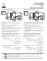
Calibration of PR-264 mA Units
1. Connect terminals [+] and [-] to the appropriate power
source.
2. Connect the DVM in series on the [-] terminal.
3. Apply low pressure to the unit and carefully adjust the zero
trimmer [Z] to obtain desired low output.
4. Apply high pressure to the unit and adjust span trimmer [S]
to obtain the desired high output pressure.
5. Repeat steps 3 and 4 until desired calibration is achieved.
All units are factory calibrated to meet or exceed published
specifications. If field adjustment is necessary, follow the
instructions below.
MAINTENANCE
Regular maintenance of the total system is recommended to
assure sustained optimum performance.
FIELD REPAIR
None. Replace with a functional unit.
WARRANTY
See Data Sheet for additional information.
Calibration of PR-264 VDC Units
1. Connect terminals [+] and [-] to the appropriate power
source. The [-] terminal is also the negative output terminal.
2. Connect the DVM on DC volts across [0] and [-] terminal.
3. Apply low pressure to the unit and carefully adjust the zero
trimmer [Z] to obtain desired low output.
4. Apply high pressure to the unit and adjust span trimmer [S]
to obtain the desired high output pressure.
5. Repeat steps 3 and 4 until desired calibration is achieved.
Figure 7 – PR-264 Pressure Transducer dimensions shown in inches and
millimeters (mm).
For Technical / Application Assistance call your nearest office
8189 Century Boulevard • Minneapolis, MN 55317-8002 • USA
800-843-5116 • 952-556-4900 • Fax 952-556-4997
[email protected] • www.mamacsys.com
EUROPE
Baird House, Units 6 & 7
Dudley Innovation Centre
Pensnett Estate • Kingswinford
West Midlands • DY6 8XZ
United Kingdom
01384-271113 • Fax 01384-271114
AUSTRALIA
4 Arminger Court, Unit 2
Holden Hill • S.A. 5088
Australia
08-8359-4333 • Fax 08-8395-4433
CANADA
155 McIntosh Drive, Unit 5
Markham • Ontario • L3R 0N6
Canada
905-474-9215 • Fax 905-474-0876
ASIA
No. 22 Lorong 21A Geylang #11-02
Prosper Industrial Building
Singapore • 388421
656-3927273 • Fax 656-3927276
MAMAC Systems, Inc., reserves the right to change any specifications without
notice to improve performance, reliability, or function of our products.
NOTE: The PR-264 is a highly accurate device. For
applications requiring a high degree of accuracy, the use of
laboratory quality meters and gauges are recommended.
TI.264-04
RoHS
RoHS
RoHS


