background image

13

11/07

125 i.e. - 160 i.e.

CHECK LEVEL/ TOP UP

• Cold engine
• Vehicle on level ground.
• Place a drip pan under the engine.
• Unscrew the oil filler screw (A).
• If necessary, top up with oil specified in the lubricant

chart until the oil starts to overflow.

• Screw on the screw (A).

F. 11

TRANSMISSION OIL

CHANGE

If there is any debris or water in the brake fluid, it is essential that it be completely changed and the brake system must be bled. Excessive elasticity in the
brake lever is usually an indication that air is in the system.

CHANGE

• After the first 1,000 Km
• Every 12,000 Km

• Cold engine
• Vehicle on level ground
• Place a drip pan under the engine.
• Unscrew the oil filler screw (A).
• Unscrew the drain screw (B)
• Drain out all the used oil.
• Clean the threads of the drain screw and screw back on.
• Refill the crankcase with oil specified in the lubricant

chart until the oil starts to overflow.

• Screw back on the screw (A).
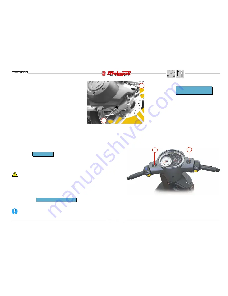
CHECK

• Visually check by way of the warning signal (S) located on the front and back

brake reservoir, with the vehicle on level ground and perfectly straight.

• The fluid level must be 3mm from the lower limit of the warning signal.

BRAKE FLUID

A

B

S

S

F. 12

every 30 days

Every 12,000 Km or 24 months

Do not mix different oil types when topping off.

Summary of Contents for Centro 125

Page 1: ......

Page 2: ...bike in order to make sure the topics the technical and safety concepts are clearly understood and the manual can be used as a sure reference text All checks maintenance repairs or replacements of sp...

Page 3: ...he topics dealt with in the page NOTE The meaning of the symbols should be duly memorised as their scope is to avoid having to repeat basic technical concepts or safety recommendations Cs Torque wrenc...

Page 4: ...ician MECHANICAL MAINTENANCE Operations to be performed only by an expert mechanic ELECTRICAL MAINTENANCE Operations be performed only by an expert electrical electronic technician IGNITION KEY ON ON...

Page 5: ...eeds repairing Prepare the components that are likely to be replaced and all the original spare parts you may need Use only the original spare parts Mark the components that may be mis placed during r...

Page 6: ...s use low flash point solvents to clean the vehicle components When welding make sure that there are no flammable liquids in the vicinity Never suck from or blow into the fuel pipe Never leave the eng...

Page 7: ...1234 1234 1234 1234 1234 1234 1234 1234 1234 1234 1234 1234 1234 1234 1234 1234 1234 1234 1234 1234 1234 1234 1234 1234 1234 1234 1234 1234 1234 1234 1234 1234 1234 1234 1234 1234 1234 1234 1234 1234...

Page 8: ...stem wet sump SPARK PLUG Type NGK DPR7EA9 TRANSMISSION Primary drive automatic transmission by V belt speed change gear Final by gears Automatic centrifugal dry clutch FUEL SYSTEM Electronic fuel inje...

Page 9: ...dentification data is pursued by the Law Minimum tread depth is 2 mm There are T W I marks all around the tyre sides These correspond to tyre wear indicators situated in the tyre s tread if there is n...

Page 10: ...ly if the vehicle is used in rainy weather in dusty places or on rough terrain Due to their simplicity checks with no asterisk CAN also be carried out by technicians not authorised by MALAGUTI but und...

Page 11: ...E NOTE Use only recommended products LUBRICANTS ENGINE OIL 4 STROKE CLASS 10W 40 ENGINE TRANSMISSION OIL CLASS 10W 40 AIR FILTER LUBRICANT AIR FILTER OIL RADIATOR FLUID TOP FLUID BRAKE CIRCUIT FLUID B...

Page 12: ...clockwise Check the fluid level in the inspection window C found under the shield If it needs to be topped up use the product specified in the lubricants chart Use unleaded fuel A Do not remove the ca...

Page 13: ...in out Remove the filter plug F Wash the screen 1 with solvent or if it is damaged replace it Check the wear conditions of the O Ring 3 and replace if necessary Reassembly O Ring 3 Spring 2 Screen 1 a...

Page 14: ...GE After the first 1 000 Km Every 12 000 Km Cold engine Vehicle on level ground Place a drip pan under the engine Unscrew the oil filler screw A Unscrew the drain screw B Drain out all the used oil Cl...

Page 15: ...the right brake fluid reservoir B to the highest level Remove the rubber hood C of the bleeder screw V and insert a rubber tube to recover the brake fluid Pump the right brake lever D prime it and bri...

Page 16: ...ness of the brake pads as shown in the illustration The minimum thickness of the brake pad friction material must not be less than 2mm Replace the pads if they are close to the allowed limit or if the...

Page 17: ...the strength of the spring increase in load SHOCK ABSORBER ADJUSTMENTS 5 adjustment positions are included 1 driver only to 75 kg 2 driver only over 75 kg 3 driver and case 4 driver and passenger 5 d...

Page 18: ...17 11 07 125 i e 160 i e LOCATION OF THE MAIN ELECTRICAL AND ELECTRONIC ELEMENTS F 24...

Page 19: ...18 11 07 125 i e 160 i e F 25...

Page 20: ...automatically reappear Seconds readout Press the top button twice to restore the initial configuration press the button again To set the clock and calendar use the two buttons on the right hand side o...

Page 21: ...To not damage the injection system never operate the START button if the fuel tank is empty or turn the key switch to ON Iftheenginedoesnotstart releasethestarter switch wait a moment and then press i...

Page 22: ...d when projected on a wall LIGHT BEAM ADJUSTMENTS Place the vehicle in gear 10 m from a wall Turn on the low beam and keep the vehicle vertical without the kickstand and without people sitting on it C...

Page 23: ...ng the operations described above be very careful not to damage the near by parts transmission cables gaskets etc LIGHT BULB REPLACEMENT Remove the number plate light see the next paragraph Remove the...

Page 24: ...the fuse and replace it with one having equal capacity Spare fuses are located inside the compartment S Do not replace fuses with others that have a higher capacity as it could seriously damage the e...

Page 25: ...he battery from its housing unless the special electrical outlet is used Disconnect cables It is a good rule to recharge using amperage that is equal to 1 10 of the power of the battery charger Remoun...

Page 26: ...with small clockwise and anti clockwise movements then unscrew the spark plug Examine the condition of the sparkplug Deposits and colorations of the insulator provide useful information on the thermal...

Page 27: ...cover sliding it towards the rear part Unscrew the window holder stud bolt B F 44 F 47 F 45 F 48 B A D V2 NOTE The left stud bolt is noted by the groove C F 46 C REAR VIEW MIRRORS Uncover and loosen...

Page 28: ...partially extract the handlebar unit carefully as to not damage the paint of the under shield or rip the electrical headlight wires To clear the front handlebar cover push the area indicated in the f...

Page 29: ...5 4 ACCESS AFTER REMOVING THE FRONT HANDLEBAR COVER 1 Clock connector 2 Clock fastened with screws V2 3 Front brake stop switch 4 Rear brake stop switch 5 Dashboard connectors 6 Hydraulic front brake...

Page 30: ...0 i e FRONT SHIELD V2 W Remove the shield with moderation being careful to not damage the hooking elements Unscrew the screws V5 to separate the grille from the shield F 56 F 57 F 58 F 59 V2 V2 1 10 W...

Page 31: ...E SHIELD A Electric fan B Radiator C Radiator cap D Diagnosis socket E Electric fan connector F Antitheft preset connector G Key switch connector D2 3 20 SEAT D2 HELMET COMPARTMENT Cap A Droplet catch...

Page 32: ...F 65 F 66 F 67 V5 5 20 V5 V2 SEAT BLOCKING DEVICE V2 V2 3 20 Remove the locking opening unit complete with the transmission cable V5 Partially lift the helmet compartment as it is constrained by the...

Page 33: ...compartment Fuel tank Fuel level gauge A Fuel level gauge connector B Fuel Pump C Pump connector D F 68 F 69 1 Temperature gauge coolant 2 Inlet air temperature sensor connector 3 T P S connector 4 I...

Page 34: ...mains as it was originally It is advisable to mark the correct position before removal Check the condition of the gaskets L and replace them if necessary F 71 A I B L FUEL PUMP Disconnect the connecto...

Page 35: ...connector D Disconnect the gas hose F pressing on the fitting with one finger R Keep a rag close by to swab up any leaking fuel Open the clamp T Disconnect the connector H Unscrew the screws v4 being...

Page 36: ...5 i e 160 i e F 73 F 74 C B A BATTERY COVER COMPARTMENT V3 Door A ACCESS Battery B Spark plugs pipette C V3 NOTE For information concerning the battery consult page 24 F 76 F 75 R W V2 W Washer R SIDE...

Page 37: ...d take it off by pushing on the front part being careful to not damage the hooking points C F 80 be careful not to lose the prestoles P When remounting insert the strut in the front drive A ACCESS 1 E...

Page 38: ...he screw V holding the self locking nut D F 83 V3 REAR FAIRING including the foot rest panel V Clean and grease the fulcrum pin P Unscrew the screws V remove the pillion staff and recuperate the under...

Page 39: ...38 11 07 125 i e 160 i e A V REARHANDLE Cap A V F 87 F 88 V2 V B Remove the rear handle including the opening locking seat device V2 Bushing B F 85 F 86 V V2 43 15...

Page 40: ...F 89 V2 V2 V REAR LIGHT UNIT V2 Rear light frame assembly B Rear light glass assembly C Number plate light support A F 91 F 92 Carefully take out the rear light unit Disconnect the wires NUMBER PLATE...

Page 41: ...e 160 i e F 94 F 95 Lift slightly the rear fairing complete with the footrest panel and number plate holder guards Take the fairing out of the frame as illustrated in figure FULL REAR FAIRING V2 F 93...

Page 42: ...relay 6 Pick up connector 7 Ground assembly 8 Regulator connector system connector NOTE Access to the various mechanical components can be deduced from the illustrations F 96 The reassembly stage of...

Page 43: ...42 11 07 125 i e 160 i e LEFT SIDE 1 Ignition coil 2 Valve manage minimum IDLE 3 Electronic control unit 4 Voltage regulator 5 Rollover sensor 6 Horn 7 Fuel hose fastening clamp F 97 2 1 1 5 4 3 6 7...

Page 44: ...nnector N V2a IGNITION COIL Disconnect the connector B Unscrew the screws V2 and remove the coil complete with the support staff ROLLOVER SENSOR Disconnect the connector C Free the sensor D from its h...

Page 45: ...44 11 07 125 i e 160 i e REAR FAIRING BREAKDOWN FROMTHE FOOT REST PANEL F 99 F 100 V3 V3 V3 REAR FAIRING BREAKDOWN FROMTHE NUMBER PLATE HOLDER GUARD V3...

Page 46: ...V2 5 10 V2 A F 102 V4 B Open carefully the leg shield on the right side Remove the fuse holder box C Disconnect the connector D Remove the leg shield unit D C V 5 10 V4 2 10 V Extract the cover B of t...

Page 47: ...eservoir E Handlebar fixing nuts F Steering wheel play regulator ferrules A Front turn signals NOTE It is not necessary to move the leg shield to replace the front turn signals They are accessible thr...

Page 48: ...with a wrench V2 A V FRONT BRAKE DISC When removing the front wheel check the condition of the brake disc In case of deep scoring or if the thickness is below the mi nimum limit of 3 5 mm remove it by...

Page 49: ...pouring the fluid in a special container for proper disposal in accordance with specific waste disposal laws V2 Remove the calliper Hydraulic oil is corrosive and may cause personal injury Remove the...

Page 50: ...16 FRONT MUDGUARD V Clamp A V3 V3 3 10 V2 Spacer B Remove the mudguard P Do not forget to remount the spacers B and clamps A C V1 Clamp C FRONT SHIELD Lower screws W F 115 Top screws V Take out the sh...

Page 51: ...g nut B of the odometer cable Remove with care the rear handlebar cover including the dashboard F 118 V4 HANDLEBAR CONTROLS V4 Disconnect the throttle transmission C Disconnect the connectors D E BRAK...

Page 52: ...de the pin off H taking care not to damage the cables and tubes Slide off the grips D 50 20 ELECTRIC FAN AND RADIATOR Before any operations on the cooling system check that the fluid is below 50 C Rem...

Page 53: ...ter the radiator is reassembled filled with fluid and tested with the engine idling for a few minutes an abnormal rise in temperature is found manually bleed it by following these steps Partially lift...

Page 54: ...ooling system check that the fluid is below 50 C Place an appropriate drain pain under the expansion tank Disconnect the tube A and empty the expansion tank remove the filling cap B to make it easier...

Page 55: ...20 To check the oil level and to change oil see page 16 FORK LEG Loosen V Raise the fork leg a few millimetres A Take out the elastic ring B Slide out the fork leg A downwards V A B FULL FORK Upper r...

Page 56: ...ng on the muffler and the exhaust pipe ensure that the components are cool V3 Loosen the clamp fixing screws V of the muffler exhaust pipe Remove the muffler Free the O2 sensor cables from the various...

Page 57: ...e with the engine inserting the gasket 2 that should be replaced if they are deteriorated Screw and tighten the nuts D2 Insert the gasket 3 Insert the muffler 4 on the manifold exhaust Screw and tight...

Page 58: ...AR MUDGUARD Right side V2 V 3 5 20 V2 3 5 20 Left side V When remounting the rear mudguard do not forget to insert the bushing A and the washers B C Check the inserted prestole D is properly F 143 F 1...

Page 59: ...e clamps B F 147 Disconnect the vapour recovery tube C1 F 147 Cut the ties E Disconnect the connector F Inlet air temperature sensor Loosen the clamps G F 146 F 147 C E F A The ties that have been cut...

Page 60: ...5 remove the cover and take out the filtering element Remove the whole air intake system To remove the intake air sensor A unscrew the screws V2A F 149 F 150 F 151 A A V5 B Unscrew the fixing screws V...

Page 61: ...ted Apply oil for air filters on the entire surface of the filter eliminating any extra oil the result should be a uniformly impregnated filter without excess oil dripping off If the filter element is...

Page 62: ...d in a special container for disposal in accordance with specific waste disposal laws Unscrew the screws V2 and remove the calliper Brake fluid is corrosive and can cause personal injury Remove the ca...

Page 63: ...57 D V2 H C E C I B G F A V2 D 100 20 Unscrew the wheel nut D Unscrew the fixing screws V of the slider arm Extract the external spacer A Remove the slider arm B Slide off the wheel pin the internal s...

Page 64: ...E Removebeforehand Rear fairing page 40 Rear mudguard page 57 Lower fixing screws shock absorbers page 56 Air filter unit page 59 Muffler page 55 Slider arm page 62 F 159 V4 Apply Loctite threa dlocke...

Page 65: ...part of the motorcycle before sliding off the engine pin It is advisable to have a second operator available to help carry out this operation Removing the engine from the frame is a task that should...

Page 66: ...65 11 07 125 i e 160 i e CABLE POSITIONING PIPE SYSTEM AND ANCHORING TIES F 164 F 165...

Page 67: ...66 11 07 125 i e 160 i e F 167 F 166...

Page 68: ...67 11 07 125 i e 160 i e F 168...

Page 69: ...68 11 07 125 i e 160 i e F 169...

Page 70: ...69 11 07 125 i e 160 i e F 170...

Page 71: ...70 11 07 125 i e 160 i e F 171...

Page 72: ...71 11 07 125 i e 160 i e F 172...

Page 73: ...72 11 07 125 i e 160 i e F 173...

Page 74: ...73 11 07 125 i e 160 i e F 176 F 174 F 175...

Page 75: ...74 11 07 125 i e 160 i e F 177 F 178...

Page 76: ...75 11 07 125 i e 160 i e F 179...

Page 77: ...76 11 07 125 i e 160 i e F 180...

Page 78: ...77 11 07 125 i e 160 i e F 181...

Page 79: ...78 11 07 125 i e 160 i e F 182 F 184 F 183...

Reviews: