background image

6

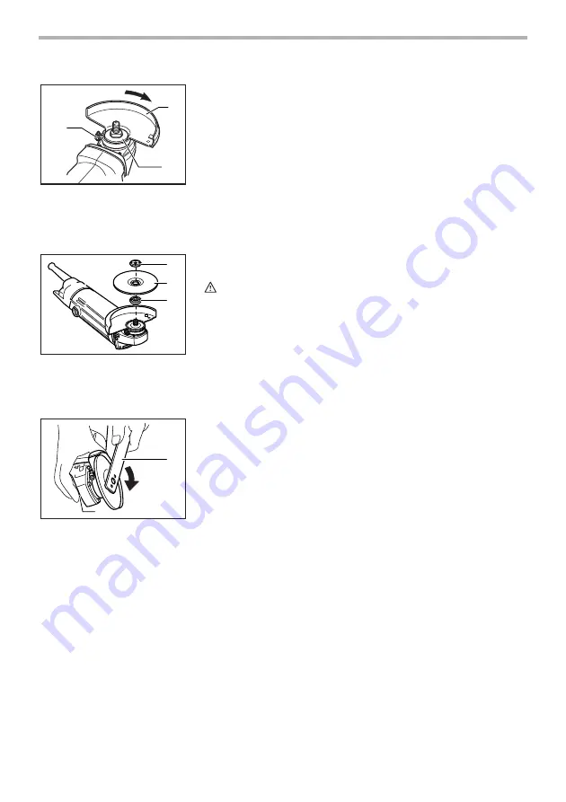
Installing the wheel guard

Mount the wheel guard with the tab on the wheel guard band aligned with the
notch on the bearing box. Then rotate the wheel guard 180° clockwise. Be
sure to tighten the screw securely.

Installing or removing depressed center wheel 
(optional accessory)

CAUTION:

Always be sure that the tool is switched off and unplugged before
installing or removing the wheel.

Mount the inner flange onto the spindle. (THE SIDE WITH THE RUBBER
SURFACE SHOULD CONTACT THE WHEEL.) Fit the wheel on over the inner
flange and screw the lock nut onto the spindle.

To tighten the lock nut, press the shaft lock firmly so that the spindle cannot
revolve, then use the lock nut wrench and securely tighten clockwise.

To remove the wheel, follow the installation procedure in reverse.

1. Wheel guard

2. Bearing box

3. Screw

3

1

2

001647

1. Lock nut

2. Depressed center wheel

3. Inner flange

1. Lock nut wrench

2. Shaft lock

1

2

3

001648

1

2

001649

Summary of Contents for MT954

Page 1: ...U C T I O N M A N U A L WARNING For your personal safety READ and UNDERSTAND before using SAVE THESE INSTRUCTIONS FOR FUTURE REFERENCE Angle Grinder MODEL MT954 MODEL MT958 MODEL MT959 006847 DOUBLE I...

Page 2: ...use tools for purposes not intended for example do not use circular saws to cut tree limbs or logs 8 Dress properly Do not wear loose clothing or jewellery they can be caught in moving parts Rubber g...

Page 3: ...rying out any work on the tool 3 Keep guards in place 4 Use only wheels with correct size and wheels having a maximum operating speed at least as high as the highest No Load Speed marked on the tool s...

Page 4: ...in dusty conditions If it should become necessary to clear dust first discon nect the tool from the mains supply use non metallic objects and avoid damaging internal parts 26 When use cut off wheel al...

Page 5: ...ool always be sure that the tool is switched off To start the tool move the switch lever to the I position To stop the tool move the switch lever to the O position ASSEMBLY CAUTION Always be sure that...

Page 6: ...removing the wheel Mount the inner flange onto the spindle THE SIDE WITH THE RUBBER SURFACE SHOULD CONTACT THE WHEEL Fit the wheel on over the inner flange and screw the lock nut onto the spindle To t...

Page 7: ...wheel has been rounded off by use the wheel may be worked in both A and B directions MAINTENANCE CAUTION Always be sure that the tool is switched off and unplugged before carrying out any work on the...

Page 8: ...Makita Corporation 884487B987...

Reviews: