P
18
/
18
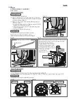
Fig. D-09
W
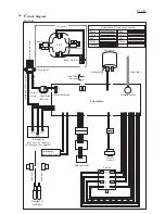
iring diagram
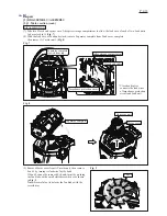
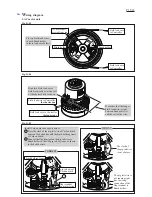
2. Wiring in Separator complete
Impedance
protection circuit
rib
Lead wires of Impedance protection circuit
of Controller must be routed between the ribs
as shown below.
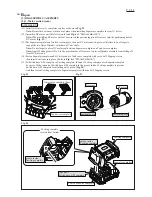
Put Insulated connectors in this space.
Fix the four lead wires in this lead wire holder.
Lead unit’s lead wire
Controller
Receptacle
(with Receptacle
sleeve)
Receptacle
Switch
Sub controller
Switch
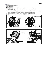
Connect Receptacles to Switch as shown below.
Do not place the slack of Lead wires
on these ribs.
Do not place the slack of Lead wires
on this portion.
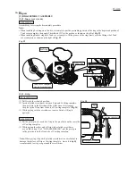
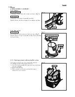
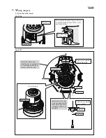
Place Lead wires
and Vinyl tube
between the boss
and the inside wall
of Separator complete.
boss
boss
inside wall of
Separator complete
Push Vinyl tube over
Pressure sensor of
Controller firmly
until it stops.
This space is for holding
two Insulated connectors.
Do not put any slack of
the other Lead wires.

