P
17
/
25
R
epair
DISASSEMBLING
ASSEMBLING
Fig. 52
Fig. 53
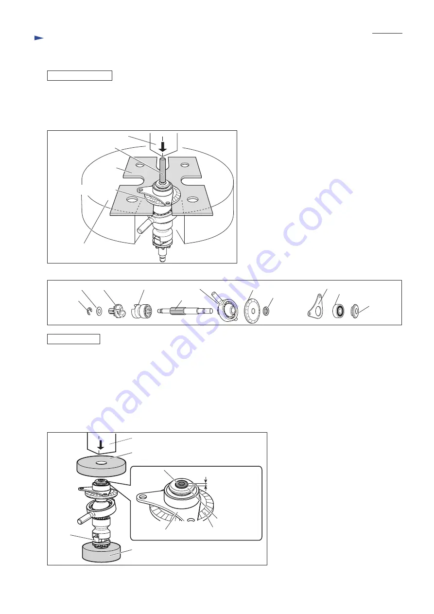
(6) Remove Stop ring EXT U-6 from Can shaft, then separate Flat washer 7, Spur gear 10 and Clutch cam A from Can shaft.
(7) Receive Spiral bevel gear 32 on 1R139 put on U-groove of Arbor press table and press out Cam shaft with 1R281
(ø7mm round bar) as drawn in
Fig. 52
.
The swash bearing section can be removed as drawn in
Fig. 53
.
Assemble the Swash bearing section carefully to the directions of each part and the order shown in
Fig. 53
.
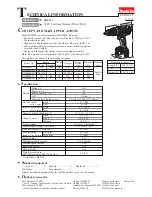
(1) Pass Cam shaft through Clutch cam A, and then receive Clutch cam A on 1R035.
(2) Pass Cam shaft through Swash bearing 10 and press-fit Spiral bevel gear 32 to Cam shaft until Spiral bevel gear stops.
(3) Pass Cam shaft through Ring 8 and Bearing retainer B, and then press-fit Ball bearing 608ZZ and Ring 8 to Cam shaft
with 1R033 carefully. Do not pinch Bearing retainer B by Ball bearing 608ZZ and Spiral bevel gear 32.
Note
: When 1mm height of Cam shaft is projected out over Ring 8, the assembling work is successful. (
Fig. 54
) Check
the height at this time.
(4) Set Spur gear 10 and Flat washer 7 in place on Cam shaft, and secure them with Stop ring EXT U-6.
[3] DISASSEMBLY/ASSEMBLY
[3]-7. Swash bearing section (cont.)
Stop ring
EXT U-6
Flat washer 7
Bearing retainer B
Spur gear 10
Arbor press
1R139
Clutch cam A Swash bearing 10 Spiral bevel gear 32
Cam shaft
Ring 8
(Flat shape)
Ring 8
(stepped)
Ball bearing 608ZZ
Spiral bevel gear 32
Arbor press table
1R281
1mm height
Cam shaft
Arbor press
Top of Ring 8
Fig. 54
Bearing retainer B
Spiral bevel gear 32
1R033
1R035
Clutch cam A


