background image

[3] DISASSEMBLY/ASSEMBLY

[3] -1. Slider (cont.)
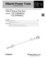
Housing (R)

Housing (R)

Housing (L)

Set plate

small slotted screwdriver

2. Remove Housing (R) by unscrewing 3x16 Tapping screws 

    (8pcs).

1. Remove Set plate before removing

    3x16 Tapping screws (8pcs).

Fig. 3

Fig. 2

Fig. 4

3. Remove Gear housing section from Housing (L).

4. Remove Shoe from Gear housing by unscrewing 

    M4x10 Countersunk head screws from the both side 

    of Gear housing.

Shoe

Model JR102D

Model JR102D

Model JR100D

Model JR100D

Shoe

Gear housing

Gear housing

5a. Remove Clamper, Pin 3 and M6x10 Hex socket set screw. So, Blade clamp is removed from Slider.

5. Remove M3x12 Hex socket head bolts (2pcs). Now, Blade holder section is removed from Slider.

Clamper

Blade clamp

M3x12 Hex socket head bolt

Blade holder section.

Pin 3

M6x10 Hex socket set screw

DISASSEMBLING

R

epair

3

/ 1

2

Summary of Contents for JR100D

Page 1: ...ries 1 3 50 2 0 3 300 13 1 2 50 2 Li ion Pipe Battery Capacity mm Cell Voltage V Capacity Ah 14 Energy capacity Wh Strokes per minutes min spm strokes per minute Length of stroke mm Yes Yes Yes No 1 2...

Page 2: ...Gear housing when removing 6902ZZ 1R281 Round Bar for Arbor 7 50 removing Ball bearing 6902ZZ from Gear housing 2 LUBRICATION Fig 1 Item No Description Shoulder pin 5 Whole surface of Pin for smooth t...

Page 3: ...e from Gear housing by unscrewing M4x10 Countersunk head screws from the both side of Gear housing Shoe Model JR102D Model JR102D Model JR100D Model JR100D Shoe Gear housing Gear housing 5a Remove Cla...

Page 4: ...to the Loop side pass Slider guide through Slider 2 Pass Sponge seal through Slider Sponge seal protruded side of Slider guide Loop side Slider Slider 3 When assembling Slider to Gear housing cover fa...

Page 5: ...its small hole for Pin 3 is aligned to the same on Slider automatically 9a Pass Pin 3 through Blade clamp and Slider 10a Assemble Clamper to Blade clamp Do not approach from the Cut portion side of B...

Page 6: ...ve Gear complete with Arbor press Fig 10 or Fig 10A Fig 10 Fig 10A 1R258 1R281 Push 1R281 by applying it on the shaft of Gear complete with Arbor press Gear complete Ball bearing 6902ZZ If only Gear h...

Page 7: ...ong tail into the slit of Blade guide And insert the short tail of the Torsion spring into the hole of Connecting sleeve Connecting sleeve Push pin 2 Insert Compression spring 2 and Push pin into the...

Page 8: ...Shoulder pin 5 assemble Driving sleeve Note Locate this gray portion to Shoulder pin 5 and mount Driving sleeve to Guide sleeve Note These concaves on Connecting sleeve fit to the inner projection of...

Page 9: ...Water pump pliers over a cloth so as not to damage it Turn Driving sleeve 90 degrees while pressing it down Now Protrusions in the Driving sleeve presisely match to Depressions on Connecting sleeve a...

Page 10: ...ever F complete and Switch lever R Or remove Pin 3 before disassembling Switch lever F complete Pin 3 1 Remove Switch lever unit Switch lever F complete and Switch lever R 2 Remove Link and Switch lev...

Page 11: ...DC Motor and Gear housing Fix the Lead wires in these Lead wire holders Do not put Lead wires on this Rib Connector Store the extra portion of Lead wires in this space designated with gray color Rib B...

Page 12: ...wires white black from connector to this place and store them in this place DC Motor Fig D 3 Fig D 4 Wiring to DC Motor Wiring to Terminal Assemble DC Motor to Housing L the Lead wires must be faced t...

Reviews: