background image

PRODUCT

P 1/ 19

T

ECHNICAL INFORMATION

Model No.

 Description

C

ONCEPT AND MAIN APPLICATIONS

HR3541FC, HR3540C
Combination Hammer 35mm (1-3/8")

Models HR3541FC and HR3540C have been developed
from HR3200C series models as 35mm (1-3/8") SDS-Max
rotary hammers.

Listed below are specification differences between the two models.
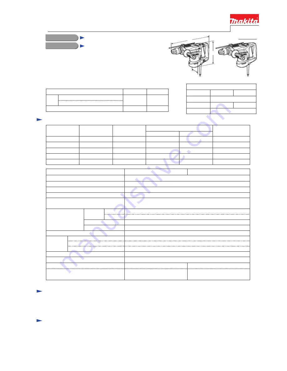
 HR3540C

Dimensions: mm (")

Width (W)

Height (H)

Length (L)

Model No.

HR3540C

HR3541FC

439 (17-1/4)

114 (4-1/2) 108 (4-1/4)

239 (9-3/8)

Active dynamic vibration absorber

Model No.

AVT

Vibration absorbing handle

Yes

No

LED Job light

Yes

No

 HR3541FC

L

H

W

HR3540C

HR3541FC

S

pecification

S

tandard equipment

O

ptional  accessories

Side handle (Bar-shaped) ................................ 1
Depth gauge .....................................................1
Grease vessel (containing 100g bit grease) ..... 1

TCT bits
Core bits
Bull points
Cold chisels
Scaling chisels
Scaling chisel (for Tile)
Grooving chisel

Clay spade
Bushing tool
Rammer
Shank (for Bushing tool and Rammer)
Chemical anchor adapter
Bit grease
Grease vessel (containing 30g hammer grease)

Plastic carrying ........................  1
Cleaning cloth ..........................  1

Note:

 The standard equipment for the tool shown above may differ by country.

Continuous Rating (W)

Voltage (V)

Cycle (Hz)

Input

Output

Max. Output (W)

110
120
220
230
240

8.6
8.2
4.4
4.4
4.4

50/60
50/60
50/60
50/60
50/60

850

---

850
850
850

300
300
300
300
300

1,100
1,100
1,100
1,100
1,100

Current (A)

Plastic carrying case
Blow out bulb
Safety goggles
Hammer service kit
Chuck adapter
Keyless drill chuck assembly

No load speed: min-

1

=rpm

Impacts per min: min-

1

=ipm

Model No.

HR3540C

HR3541FC

Europe: 4.0 (13.1), Brazil: 2.0 (6.6), Other countries: 5.0 (16.4)

Shank diameter: mm (") 

Capacities: mm (")

Torque limiter

Double insulation
Power supply cord: m (ft)

Electronic
features

Variable speed control by dial

Constant speed control

Soft start

Yes
Yes
Yes
Yes
Yes

13 (1/2)

32 (1-1/4)

315 - 630

1,650 - 3,300

Wood

Steel

35 (1-3/8)
90 (3-1/2)

Core bit

TCT bit

5.2 (11.4)

4.8 (10.6)

5.6 (12.3)

5.2 (11.4)

Net weight: kg (lbs)

18 (11/16)

Operation mode

3 modes

(Rotation only/ Rotation with hammering/ Hammering only)

Shank type 

SDS-Max

Concrete

Weight according

EPTA-Procedure 01/2003

*

: kg (lbs)

*

 includes Side handle.

Summary of Contents for HR3541FC

Page 1: ...sel containing 30g hammer grease Plastic carrying 1 Cleaning cloth 1 Note The standard equipment for the tool shown above may differ by country Continuous Rating W Voltage V Cycle Hz Input Output Max Output W 110 120 220 230 240 8 6 8 2 4 4 4 4 4 4 50 60 50 60 50 60 50 60 50 60 850 850 850 850 300 300 300 300 300 1 100 1 100 1 100 1 100 1 100 Current A Plastic carrying case Blow out bulb Safety go...

Page 2: ...emoving M6x25 Hex socket head bolt for tightening Barrel complete 1R269 Bearing extractor Removing Ball bearings 1R367 Taper sleeve Fitting Fluoride ring to Impact bolt 1 5 a Ring 38 Impact bolt Striker Piston Chuck cover a little a little approx 2 g Tool holder cap Tool holder O Ring 19 O Ring 18 Spiral bevel gear 32 Pin 7 Cylinder 25 Tool retainer Chuck ring Ring spring 25 Spring guide Spring ho...

Page 3: ...102 Armature 107 107 Oil seal 82 82 50 61 63 O ring 8 Whole portion Whole portion Whole portion The lip portion Gear teeth for smooth engaging with Gear shaft Gear teeth for smooth engaging with Gear shaft Crank room Whole portion The drum portion for smooth reciprocation in Pipe 15 O ring 18 55 57 58 102 O ring 28 O ring 16 Gear housing complete Around Spur gear 33 and Torque limiter complete Amo...

Page 4: ...base Handle Handle cover Controller Cord clamp Crank cap Motor housing Crank gear 2pcs 6pcs 1pc 1pc 1pc 1pc Crank cap cover to Crank cap Cap holder to Crank gear Controller to Motor housing Cord clamp base to Controller Cord clamp to Cord clamp base Total Total 4x18 Tapping Screw for tightening 1pc 8pcs 2pcs 4pcs 1pc Change lever to Spur gear 33 complete Rear cover to Motor housing Brush holder un...

Page 5: ...ide Remove Compression spring 52 and Spring holder Remove Ring spring 25 Remove Chuck ring 4x18 Tapping screw 2pcs 1 Remove Controller and Handle section and then upright the machine as illustrated in Fig 5 2 Disassemble Chuck section as illustrated in Fig 6 Take the disassembling step in reverse Refer to Figs 6 and 5 Chuck cover Chuck cover Ring spring 25 1R212 Chuck ring Chuck ring Spring guide ...

Page 6: ...38 Flat washer 39 1 Remove Ring 38 Urethane ring 38 and Flat washer 39 2 Apply magnetized Screwdriver to Pin 6 Screwdriver magnetized with 1R288 Urethane ring 38 Pin 6 4pcs Cylinder 25 Pin 6 Tool holder Tool holder Cylinder 25 3 Align Tool holder s hole with that of Cylinder 25 by pushing Tool holder 4 Remove Pin 6 with magnetized Screwdriver when the both holes are aligned each other Remove Tool ...

Page 7: ...have to be assembled to Cylinder 25 to fix Pin 6 as illustrated in Fig 11 Pin 6 joining Tool holder to Cylinder 25 4pcs Urethane ring 38 Flat washer and Rings has to be assembled in the following order 1 Flat washer 39 2 Urethane ring 38 3 Ring 38 Ring 38 Flat washer 39 Tool holder guide Cylinder 25 Fig 11 Fig 12 1 Disassemble Chuck section as illustrated in Figs 5 6 2 Separate Cylinder section fo...

Page 8: ...rox 90 degree Ring 13 5 Remove Slide plate from Cylinder 25 as illustrated in Fig 13 Take the disassembling step in reverse Refer to Figs 13 and 12 Join the assembled Cylinder section to Tool holder with Pin 6 Refer to Fig 8 And Secure Pin 6 with Flat washer 39 Urethane ring 38 and Ring 38 as illustrated in Fig 11 Impact bolt Rubber ring 13 Cylinder 25 Ring 13 Tool holder Fig 14 Note Ring 13 is no...

Page 9: ...er is released from Crank housing complete Disassemble Active dynamic vibration absorber by levering up with two Slotted screwdriver Active dynamic vibration absorber Phillips screwdriver Phillips screwdriver Slotted screwdriver 2 Remove Active Dynamic Vibration Absorber from Crank housing complete as illustrated in Fig 16 And disassemble as illustrated in Fig 17 Fig 16 Fig 17 Pipe holder Pipe hol...

Page 10: ... that the tip of Spring guide comes out by return force of Compression spring 10 Spring guide Assemble Active dynamic vibration absorber by pressing while maintaining the position parallel to Crank housing Spring guide Fig 18 Fig 19 5 5 Motor Section Torque Limiter Section DISASSEMBLING Fig 20 4x18 Tapping screw 2pcs 4x14 Tapping screw 2pcs 5x25 Tapping screw 2pcs 5x20 Pan head screw 2pcs Active d...

Page 11: ... can be separated completely from machine 4 Disconnect connectors to disassemble Handle section as illustrated in Fig 21 Handle section Cord clamp base 4x18 Tapping screw 2pcs Fig 21 Carbon brush Disconnection of Carbon brush with Commutator Spiral spring Carbon brush Carbon brush Spiral spring Detach Spiral spring from Carbon brush By pulling Carbon brush disconnect the contact with Armature s co...

Page 12: ...m and to prevent Torque limiter from having damage Motor housing 6 Remove Armature as illustrated in Figs 23 and 24 Fig 23 Fig 24 1R346 Note Be careful not to lose Cup washer 18 for Crank shaft Armature Handle of 1R045 Cup washer 18 Remove Torque limiter section by striking the Gear housing s edge with Plastic hammer if Torque limiter section is left on the Gear housing Remove Armature from Gear h...

Page 13: ...emaining parts as illustrated in Figs 27 and 28 Set Change lever to Rotary hammer mode If Crank cap is already removed align the triangle mark on Change lever with that on Crank cap Fig 26 Fig 27 Note When disassembling Crank cap do not move Change lever from the position illustrated in Fig 26A Remove Crank cap by unscrewing M4x16 Pan head screws And then remove Link plate M4x16 Pan head screw 5 p...

Page 14: ...ar 33 Clutch Crank shaft Conical compression spring 21 31 Flat washer 10 Flat washer 22 Key 4 Retaining ring S 20 Crank section 1 Assemble Crank section by taking the reverse of Disassembling steps Refer to Fig 30 And then mount the Crank section to Crank housing complete Note When assembling Retaining ring WR 10 to Crank shaft assemble it as illustrated in Fig 31R Crank shaft Crank shaft Retainin...

Page 15: ...ble Crank cap cover The triangle mark on Change lever has to designate the mark of Rotary hammer mode on Crank cap cover as illustrated in Fig 26 And assemble the remaining parts by taking the reverse of the disassembling steps Spiral bevel gear 37 Notches of Link arm The notches of Link arm come into sight Push Link arm into Crank housing complete until the notches of Link arm come into sight in ...

Page 16: ... screw 1pc 4x18 Tapping screw 1pc Handle cover Switch lever Switch lever Handle base Handle Section can be disassembled as illustrated below Shoulder sleeve 6 2pcs Handle Dust cover support Dust cover Lead unit Handle cover HR3540C HR3541FC Fig 35A Lead unit Switch holder complete Switch holder complete ON OFF Switch ON OFF Switch Handle Handle 5x40 Tapping Screw 2pcs Flat washer 5 2pcs Compressio...

Page 17: ...eve Cylinder 25 Compression spring 52 Spring holder Tool holder Impact bolt Barrel complete Chuck cover 27 42 43 46 28 Piston Spiral bevel gear 37 Circuit diagram Red Power Supply Cord Lead unit Lead wire white of Power supply cord is blue for some countries Switch Connector of Lead Unit Fig D 1 White Color index of lead wires sheath Black HR3540C Handle Motor Housing Lead wire black of Power supp...

Page 18: ... as illustrated on left Fix it with Lead wire holder Do not slack it between LED circuit and Lead wire holder Controller Rib Rib Rib LED Circuit Motor Housing Rear View Motor Housing Rear View Dial C Rib A of Motor housing Rib B of Motor housing Route Lead wire of Light circuit between B and C Do not put Lead wire of Light circuit on the Rib B of Motor housing Lead wire of Light circuit B Rib of c...

Page 19: ... area Fix them with Lead wire holders and Ribs Route the lead wires of Lead unit through the opening of Handle base and Handle Handle Lead wire holder Motor housing Handle base Rib Lead unit Lead wire of Power supply cord Power supply cord Connector of Lead unit Controller Cord guard B Rib of Motor housing A Rib for Controller Dial HR3541FC ...

Reviews: