

2-1. Disassembling of barrel
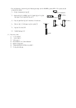
Remove the hexagon socket bolt M5x20 and then remove
the barrel.
Use the arbor press to press the top of tool holder to
remove it.
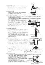
2-2. Assembling of barrel
Assemble in a way that the trace of pusher pin shown on
the right figure comes at name plate side.
3-1. Disassembling of impact bolt
Use the screw driver to shift the impact bolt in the direction of tool holder edge as shown on the bottom-
right figure.(in the direction of arrow 1)
Use the resin hammer to slightly hammer the tool holder as shown on the bottom-right figure to remove
the four points of steel ball 5 and 6.
Use the sharpened-edge tool like an eyeleteer to pull out
the O ring 11 as shown on the bottom-right figure. For
easy disconnection, use the eyeleteer while 5 mm around
of sharpened-edge tool edge is being bent by 90"around.
Use the driver edge to disconnect(push) the impact
bolt.(in the direction of arrow 2
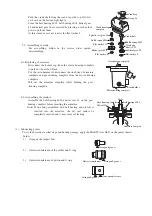
3-2. Assembling of impact bolt
Use the screw driver to insert the impact bolt into the tool
holder.
Use the sharpened-edge tool to insert the O ring 11 into the
groove of the tool holder. Move the impact bolt in the direction
of arrow to check if O ring 11 cannot be disconnected.
Before placing the steel ball 5 and 6 in the tool holder, grease
into the hole so that the steel ball cannot drop and the tool
holder can be easily set.
4-1. Disassembling of torque limiter
Use the circle clip plyer to disconnect the circle clip(shaft)S-
26 and then remove the spiral bevel gear 33, clutch cam and
compression spring 31.
If hard to disconnect the parts, shift the flat washer 26 away
from the circle clip groove since it is housed in said groove.
4-2. Assembling of torque limiter
Use care of direction of clutch cam when assembling the
torque limiter.
Engage the protruded portion with the spiral bevel gear 33
while supporting the compression spring 31 by holding the
dent face.
5-1. Disassembling of crank
To disassemble the handle set, disconnect the two points of pan head screw M5X25 connected on the
crank housing complete and then disconnect the tapping
screw PT5x25 connected on the motor housing complete.
To disassemble the motor housing complete, disconnect the
hexagon holed bolt M5x45 connected on the gear housing
complete and crank housing complete.
Separate the crank housing from the gear housing.
Use the lock nut wrench 28 to disconnect the crank cap.
Press
Tool holder
Trace of pusher pin
Steel ball 5 and 6
Tool holder
O ring 11
Impact bolt
Press
O ring 11
Impact bolt
Steel ball 5 and 6
Tool holder
Flat washer 26
Tool holder
Circle clip
(shaft)S-26
Spiral bevel
gear 33
Clutch cam
Compression
spring 31
(Spiral bevel gear 33 side)
(Compression spring 31 side)
This protruded face is almost
the same in size as the one of
cam of spiral bevel gear 33.
Direction of tool holder edge.
Arrow
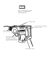
Pan head screw M5x25
Crank cap
Crank housing
complete
Gear housing complete
Motor housing complete
Handle set
Tapping screw PT5x25
Hexagon holed bolt M5x45


