5
ENGLISH (Original instructions)
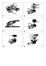
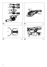
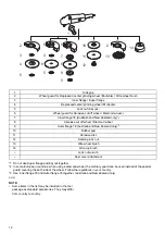
Explanation of general view
SPECIFICATIONS
• Due to our continuing program of research and development, the specifications herein are subject to change without
notice.
• Specifications may differ from country to country.
• Weight according to EPTA-Procedure 01/2003
Symbols
END202-8
The following show the symbols used for the equipment.
Be sure that you understand their meaning before use.
... Read instruction manual.
............. DOUBLE INSULATION
... Wear safety glasses.
Intended use
ENE048-1
The tool is intended for grinding, sanding and cutting of
metal and stone materials without the use of water.
Power supply
ENF002-2
The tool should be connected only to a power supply of
the same voltage as indicated on the nameplate, and can
only be operated on single-phase AC supply. They are
double-insulated and can, therefore, also be used from
sockets without earth wire.
For public low-voltage distribution systems of
between 220 V and 250 V.
ENF100-1
Switching operations of electric apparatus cause voltage
fluctuations. The operation of this device under
unfavorable mains conditions can have adverse effects to
the operation of other equipment. With a mains
impedance equal or less than 0.23 Ohms it can be
presumed that there will be no negative effects. The
mains socket used for this device must be protected with
a fuse or protective circuit breaker having slow tripping
characteristics.
General Power Tool Safety
Warnings
GEA005-3
WARNING Read all safety warnings and all
instructions.
Failure to follow the warnings and
instructions may result in electric shock, fire and/or
serious injury.
Save all warnings and
instructions for future reference.
The term “power tool” in the warnings refers to your
mains-operated (corded) power tool or battery-operated
(cordless) power tool.
Work area safety
1.
Keep work area clean and well lit.
Cluttered or dark
areas invite accidents.
2.
Do not operate power tools in explosive
atmospheres, such as in the presence of
flammable liquids, gases or dust.
Power tools
create sparks which may ignite the dust or fumes.
3.
Keep children and bystanders away while
operating a power tool.
Distractions can cause you
to lose control.
1.
Shaft lock
2.
Motor housing
3.
Lock button
4.
Handle
5.
Switch trigger
6.
Lock lever
7.
Wheel guard
8.
Screw
9.
Bearing box
10. Nut
11. Lever
12. Lock nut
13. Depressed center wheel
14. Super flange
15. Inner flange
16. Lock nut wrench
17. Abrasive disc
18. Rubber pad
19. Wire cup brush
20. Wire wheel brush
21. Abrasive cut-off wheel/diamond
wheel
22. Wheel guard for abrasive cut-off
wheel/diamond wheel
23. Outer flange 78
24. Inner flange 78
25. Exhaust vent
26. Inhalation vent
27. Commutator
28. Insulating tip
29. Carbon brush
30. Brush holder cap
31. Screwdriver
Model
GA7030/GA7030S
GA7040S
GA9030/GA9030S
GA9040S
Depressed center wheel
diameter
180 mm
230 mm
Max. wheel thickness
6.5 mm
6.5 mm
Spindle thread
M14
M14
Rated speed (n)/No load speed (n
0
)
8,500 min
-1
6,600 min
-1
Overall length
511 mm
511 mm
Net weight
6.0 kg
6.4 kg
6.3 kg
6.7 kg
Safety class
/II


