background image

7

/ 1

1

R

epair

DISASSEMBLING

[3] DISASSEMBLY/ASSEMBLY
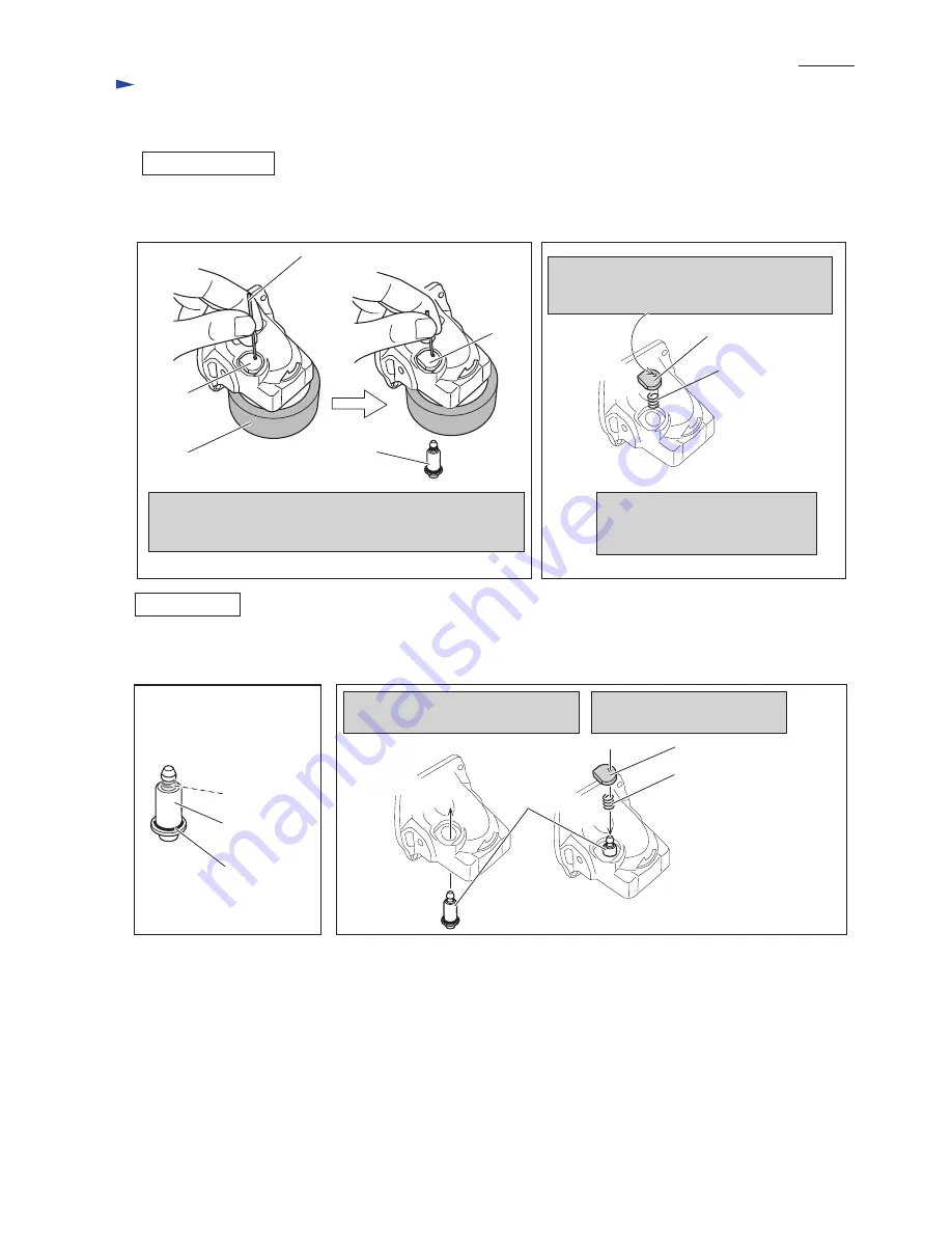
[3]-3. Shaft lock 

Fig. 17

Applying 1R268 to Shoulder pin 4 through the hole on Pin cap,
strike 1R268 with Hammer.
Shoulder pin 4 comes out from Gear housing complete.

Slowly release 1R268 from Pin cap 
carefully not to lose Compression 
spring 8.

Shoulder pin 4

Pin cap

Impossible to reuse Pin cap because removal
of Shoulder pin 4 damages the inside surface of 
Pin cap, producing plastic dust.

Pin cap

Pin cap

Compression
spring 8

1R268

Shaft lock can be disassembled as illustrated in Figs.15 and 16.

1R350

Fig. 16

Fig. 15

ASSEMBLING

Fig. 18

(1) Be sure to use a new Pin cap for replacement and to remove all the plastic dust on Shoulder pin 4.  (Fig. 17)
(2) Assemble the Parts for Shaft lock mechanism as illustrated in Fig. 18.

Plastic dust

O ring 4

Shoulder pin 4

Shoulder
pin 4

Assemble Pin cap by pressing it 
to Shoulder pin 7.

Insert Shoulder pin 4 through the hole
of Gear housing complete.

Pin cap

Compression spring 8

Summary of Contents for GA4034

Page 1: ...1 rpm Diameter Hole diameter Wheel size mm Protection against electric shock Power supply cord m ft Net weight kg lbs GA4034 100 4 Brazil Australia 2 0 6 6 Other countries 2 5 8 2 1 8 4 0 1 9 4 2 11 0...

Page 2: ...tion to lubricate Lubricant Amount 9 18 Makita grease SG No 0 7g a little 3 DISASSEMBLY ASSEMBLY 3 1 Armature Ball bearing 629DDW Ball bearing 607DDW Spiral bevel gear 10 DISASSEMBLING 4x22 Tapping sc...

Page 3: ...Note Cover the work table with something soft to avoid the damage on Gear housing before disassembling Ball bearing 629DDW Ball bearing 629DDW Retaining ring R 26 Remove Retaining ring R 26 with 1R00...

Page 4: ...g 3 Remove Ball bearing 696ZZ with 1R269 and then separate Ring spring 11 from Spindle with 1R004 Fig 12 2 Spindle Spiral bevel gear 37 and Labyrinth ring can be removed as illustrated in Fig 13 3 Rem...

Page 5: ...031 and assemble Spindle Labyrinth ring works as a shield against dust If Labyrinth ring is assembled to Spindle facing the groove surface to the upper side it does not work as a shield against dust f...

Page 6: ...ages the inside surface of Pin cap producing plastic dust Pin cap Pin cap Compression spring 8 1R268 Shaft lock can be disassembled as illustrated in Figs 15 and 16 1R350 Fig 16 Fig 15 ASSEMBLING Fig...

Page 7: ...nd two 4x70 Tapping screws Fig 19 assemble Gear housing to Motor housing temporarily 2 Tap the front portion of Gear housing with plastic hammer until Field moves half from the original position Fig 2...

Page 8: ...eath Black Brown Blue AC DC Switch models for Keppel corporation limited in Singapore etc Fig D 2 Strain relief Brown lead wire is used for some countries Blue lead wire is used for some countries Noi...

Page 9: ...holder to Switch Fig D 3 AC DC Switch models for Keppel comporation limited in Singapore etc to Switch Field lead wire red Field lead wire red Field lead wire red Field lead wire black Field lead wir...

Page 10: ...or housing Motor housing Right side view Motor housing Belly side view Rib A Rib Switch Power supply cord Rib B Field lead wires red black have to be tight in Motor housing Brush holder Pass Field lea...

Page 11: ...as not to contact Rib B Rib B Rib A Switch Power supply cord Field lead wires red black have to be tight in Motor housing Motor housing Pass Field lead wire black by Rib on the Brush holder side Motor...

Reviews: