P
7
/ 1
8
R
epair
[4] DISASSEMBLY/ASSEMBLY
[4]-5. Trimmer head ass’y (cont.)
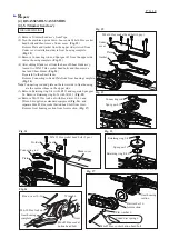
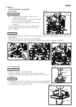
(7) Remove M8x8 Hex socket head bolt from Gear housing
complete, and insert 1R236 into the threaded hole, then
press down 1R236 to remove the assembled part of
Spiral bevel gear 12 and two Ball bearings 6000ZZ from
Gear housing complete. (
Fig. 18
)
(8) Remove two M4x16 Hex socket head bolts, and then pull
out Angular plate from Gear housing complete.
The following parts can be removed together with
Angular plate. (
Fig. 19
)
• Retaining ring S-10
• Spiral bevel gear 22
• Ball bearing 6001ZZ (2 pcs.)
• Spiral bevel gear 11
(9) Remove Retaining ring S-10 from the groove of Spiral
bevel gear 11 to disassemble the parts around Angular
plate.
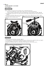
(10) Disassemble Slide lever set by unscrewing two 4x18
Tapping screws. (
Fig. 20
)
(11) Remove M5x25 Hex socket head bolt and two Stop
rings E-4 (
Fig. 21
) then separate Cover from
Pipe holder/ Joint. (
Fig. 22
)
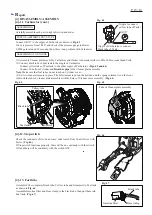
(12) Loosen four M4x20 Hex socket head bolts and then
remove Pipe holder. (
Fig. 23
)
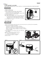
(13) Remove two M4x16 Hex socket head bolts, (
Fig. 24
)
and then press down Spindle complete in Pipe holder
with 1R247. (
Fig. 25
)
Fig. 20
Fig. 21
Fig. 22
Fig. 23
Fig. 24
Fig. 25
Fig. 18
Fig. 19
Spiral bevel gear 12
Spiral bevel
gear 22
M4x16 Hex socket head bolt (2 pcs.)
Gear housing
complete
Gear housing
complete
Angular plate
Joint
Joint
Cover
4x18 Tapping screw (2 pcs.)
Slider lever set
M5x25 Hex socket
head bolt
Stop ring E-4 (2 pcs.)
Ball bearing
6000ZZ (2 pcs.)
Ball bearing 6001ZZ
(2 pcs.)
Spiral bevel gear 11
M8x8 Hex socket
head bolt
1R236
Rod 5
(2 pcs.)
Pipe
holder
Pipe holder
M4x16
Hex
socket
head bolt
(2 pcs.)
Cover
Spindle complete
1R247
M4x20 Hex
socket head
bolt (4 pcs.)


