background image

12

4

2

9

12

3

2

11

8

9

10

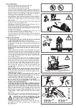
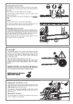
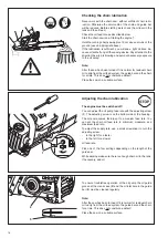
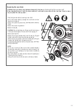
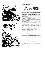
Replace the sprocket guard (3).

NOTE:
The chain must be placed on the chain catcher 

(11) and remain there.

Tighten the nuts (2) only hand‑tight to begin with.

Lift the chain (9) over the sprocket (8).
CAUTION:
Do not insert the chain between the chain sprocket and the 

disc.
Guide the chain from above about halfway into the groove (10

on the guide bar.
CAUTION:
Note that the cutting edges along the top of the chain must  

point in the direction of the arrow!

Tightening the saw chain

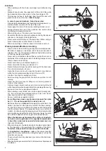
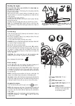
Turn the chain tensioning screw (4) to the right (clockwise) until 

the saw chain catches in the groove on the lower side of the 

guide bar (see circle).
Slightly lift the end of the guide bar and turn the chain adjusting 

screw (4) to the right (clockwise) until the chain rests against 

the bottom side of the guide bar.
While still holding up the tip of the guide bar, tighten the retaining 

nuts (2) with the universal wrench.

Pull the chain (9) around the sprocket nose (12) of  the guide  

bar in the direction of the arrow.

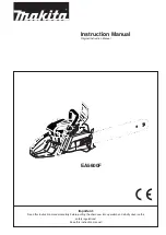
Summary of Contents for EA5600F

Page 1: ...Read this instruction manual carefully before putting the chain saw into operation and strictly observe the safety regulations Keep this instruction manual EA5600F Instruction Manual Original Instruct...

Page 2: ...ce the risk of serious or fatal injury persons with a medical device should consult with their physician and the manufacturer of the device before operating this equipment Table of contents Page Deliv...

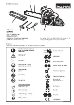
Page 3: ...e following symbols on the saw and in the Instruction Manual Read instruction manual and follow the warning and safety precautions Particular care and caution Forbidden Wear protective helmet eye and...

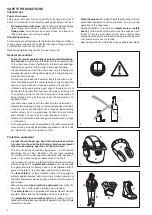
Page 4: ...to accept liability for others Never use the chain saw after having consumed alcohol drugs or medication A fire extinguisher must be available in the immediate vicinity when working in easily inflamm...

Page 5: ...r and the function of the throttle lever lock thecleanlinessanddrynessofthehandles andthefunction of the ON OFF switch Putthechainsawonlyintooperationifitiscompletelyassembled Never use the chain saw...

Page 6: ...ithin the elongated swivelling range of the saw 12 Use the chain saw for sawing wood only Avoid touching the ground with the chain saw while it is still running Never use the chain saw for lifting up...

Page 7: ...g risk of stumbling d the next working place is at least 2 1 2 tree lengths away 17 Before cutting down the tree check the direction of fall and make sure that there are neither people nor objects wit...

Page 8: ...ectly 22 Operate the chain saw only at a low noise and emission level For this ensure the carburetor is adjusted correctly Regularly clean the chain saw Regularly check the tank cap for tightness Obse...

Page 9: ...NGK BPMR 7A or spark plug Type Electrode gap mm 0 5 Fuel consumption at max load per ISO 7293 kg h 1 4 Specific consumption at max load per ISO 7293 g kWh 430 Fuel tank capacity cm3 570 Chain oil tan...

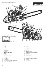
Page 10: ...rburetor Identification plate 16 Indicate when ordering spare parts Year of manufacture Denomination of components 14 Fuel gauge 15 Fuel pump Primer 16 Identification plate 17 Starter grip 18 Combinat...

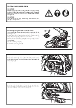
Page 11: ...elease the chain brake by pulling the hand guard 1 in direc tion of arrow Unscrew retaining nuts 2 Pull off the sprocket guard 3 PUTTING INTO OPERATION CAUTION Before doing any work on the guide bar o...

Page 12: ...along the top of the chain must point in the direction of the arrow Tightening the saw chain Turn the chain tensioning screw 4 to the right clockwise until the saw chain catches in the groove on the...

Page 13: ...aging the chain brake braking If the kickback is strong enough the sudden acceleration of the guide bar combined with the inertia of the hand guard 1 will automatically actuate the chain brake To enga...

Page 14: ...filling it into the chain saw tank It is not wise to add more engine oil than specified to ensure safe operation This will only result in a higherproductionofcombustionresidueswhichwill pollutetheenvi...

Page 15: ...pump and the sawing device In case of damage caused by using waste oil or unappropriate chain oil the product guarantee will be null and void Your salesman will inform you about the use of chain oil...

Page 16: ...lace the saw on a suitable surface To ensure troublefree operation of the oil pump the oil guide groove at the crank case 2 and the oil inlet bore in the guide bar 3 must be cleaned regularly Note Aft...

Page 17: ...ated by the palm of the hand and press the throttle trigger 4 CAUTION The engine must be put in idle immediately after starting If this is not done the clutch can be damaged Now disengage the chain br...

Page 18: ...ut the cover back on 6 Symbol Normal operation Symbol Winter operation Checking the chain brake The chain brake must be checked before every use of the saw Start the engine as described above have a s...

Page 19: ...mplete assembly and testing of the saw Idle speed adjustment must only be undertaken when the engine is warm with a clean air filter and properly in stalled guide bar and chain Use a screwdriver 4 mm...

Page 20: ...or right when sawing This is caused by uneven sharpening of the chain Important Sharpen frequently but without removing too much metal Generally 2 or 3 strokes of the file will be enough Have the chai...

Page 21: ...then the standerd for all other cutters of the chain New saw teeth must be filed to the exact same shape as the used teeth including on their running surfaces File depending on chain type 90 or 10 to...

Page 22: ...o residues or foreign matter remaining in the oil guide groove 4 or on the chain tensioner 5 To install the guide bar saw chain and sprocket guard see PUTTING INTO OPERATION NOTE The chain brake is a...

Page 23: ...ers see Extract from the spare parts list For replacing the guide bar chain and sprocket see PUTTING INTO OPERATION NOTE Do not use a new chain with a worn chain sprocket Replace the chain sprocket af...

Page 24: ...ric If the filter is very dirty wash it out in a lukewarm solution of dishwash ing liquid and rinse it out from the inside under running water Note that the filter does not need to be cleaned until th...

Page 25: ...the spark plug Use only the combination wrench supplied with the saw to remove the spark plug Electrode gap The electrode gap must be 0 5 mm CAUTION Use only the following spark plug NGK BPMR 7A Check...

Page 26: ...s in the notch see the arrow in the closeup Thread a new cable dia 3 8 mm length 1000 mm as shown in the illustration don t forget the washer 11 and knot both ends as shown Pull the knot 12 into the c...

Page 27: ...y insert a new return spring cassette and press down until it engages Assemble the cable drum and tension the return spring see page 26 Replacing the starter spring NOTE If the spring 7 in the Feather...

Page 28: ...replacement pull it out through the tank filler neck using a piece of wire bent at one end to form a hook 1 Cleaning the air filter compartment fan com partment Remove cover Remove the fan housing CAU...

Page 29: ...flow 28 Fan compartment Clean to maintain good cooling air flow 28 Cylinder fins Clean to maintain good cooling air flow 28 Spark plug Check and replace if necessary 25 Muffler Check tightness of mou...

Page 30: ...s will automatically invalidate the MAKITA product guarantee Guarantee MAKITA guarantees the highest quality and will therefore reimburse all costs for repair by replacement of damaged parts resulting...

Page 31: ...or piston rings defective Outside Spark plug does not seal Mechanical Starter does not engage Spring in starter broken broken parts malfunction inside the engine Warm start difficulties Carburetor Fue...

Page 32: ...24 25 26 27 28 29 30 23 7 6 5 4 19 1 2 3 14 13 17 10 11 12 18 20 21 22 15 16 Extract from the spare parts list Use only original MAKITA parts For repairs and replacement of other parts see your MAKITA...

Page 33: ...1 Offset screwdriver 6 944 340 001 1 Carburetor screwdriver 7 010 114 200 1 Suction head 8 181 114 202 1 Fuel tank cap cpl 9 963 229 036 1 O Ring 29 3 x 3 6 mm 10 181 163 050 1 Return spring pack comp...

Page 34: ...34 EC Declaration of Conformity For European countries only The EC declaration of conformity is included as Annex A to this instruction manual...

Page 35: ...35...

Page 36: ...tist Vinkstraat 2 3070 Kortenberg Belgium and Makita Corporation Anjo Aichi Japan Form 995 705 728 2017 04 GB Specifications subject to change without notice To find your local distributor please visi...

Reviews: