


P 4/ 6
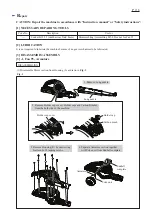
Fig. 3
R
epair
ASSEMBLING
1. Assemble Motor section while fitting two notches of
Yoke unit to two projections of Housing (L).
2. Be sure that Hanger is mounted to the following
place before mounting Housing (R).
two notches of
Yoke unit
Hanger
two projections
of Housing (L)
Assemble by reversing the disassembly procedure. (
Figs. 2
and
1
)
Note
:
(1) Do not forget to set Flat washer 5 and Flat washer 8 in place. (
Fig. 2
)
(2) Fit two notches of Yoke unit to two projections on Housing (L). (
Fig. 3
)
(3) Before assembling Housing (R), mount Hanger on Housing (L). (
Fig. 3
)
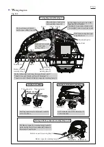
[3] -2. Switch unit
DISASSEMBLING
Fig. 4
Connector
(1) Disassemble Housing (R) from Housing (L) as drawn in
Fig. 1
.
It is not necessary to remove Motor section.
(2) Remove Switch unit by disconnecting Connectors as drawn in
Fig. 4
.
Connector
Switch unit
Switch unit
[3] DISASSEMBLY/ASSEMBLY
[3] -1. Fan 95, Armature (cont.)


