


12 ENGLISH
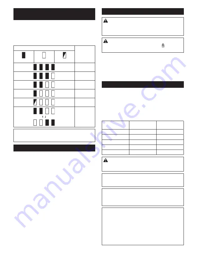
Indicating the remaining battery
capacity
Only for battery cartridges with the indicator
►
Fig.2:
1.
Indicator lamps
2.
Check button
Press the check button on the battery cartridge to indi
-
cate the remaining battery capacity. The indicator lamps
light up for a few seconds.
Indicator lamps
Remaining
capacity
Lighted
Off
Blinking
75% to 100%
50% to 75%
25% to 50%
0% to 25%
Charge the
battery.
The battery
may have
malfunctioned.
NOTE:
Depending on the conditions of use and the
ambient temperature, the indication may differ slightly
from the actual capacity.
Tool / battery protection system
The tool is equipped with a tool/battery protection sys
-
tem. This system automatically cuts off power to the
motor to extend tool and battery life. The tool will auto
-
matically stop during operation if the tool or battery is
placed under one of the following conditions:
Overload protection
When the battery is operated in a manner that causes
it to draw an abnormally high current, the tool automat
-
ically stops without any indication. In this situation, turn
the tool off and stop the application that caused the tool
to become overloaded. Then turn the tool on to restart.
Overheat protection
When the tool or battery is overheated, the tool stops
automatically and the lamp blinks. In this case, let the
tool and battery cool before turning the tool on again.
Overdischarge protection
When the battery capacity is not enough, the tool stops
automatically. In this case, remove the battery from the
tool and charge the battery.
Switch action
WARNING:
Before installing the battery car-
tridge into the tool, always check to see that the
switch trigger actuates properly and returns to
the "OFF" position when released.
CAUTION:
When not operating the tool,
depress the trigger-lock button from side to
lock the switch trigger in the OFF position.
►
Fig.3:
1.
Switch trigger
2.
Trigger-lock button
To prevent the switch trigger from accidentally pulled,
the trigger-lock button is provided. To start the tool,
depress the trigger-lock button from A side and pull the
switch trigger. Release the switch trigger to stop. After
use, press in the trigger-lock button from B side.
Speed change
The revolutions and blows per minute can be adjusted
by turning the adjusting dial. The dial is marked 1 (low
-
est speed) to 5 (full speed).
►
Fig.4:
1.
Adjusting dial
Refer to the table below for the relationship between the
number on the adjusting dial and the revolutions and
blows per minute.
Number
Revolutions per
minute
Blows per minute
5
500
2,900
4
470
2,700
3
380
2,150
2
290
1,650
1
250
1,450
CAUTION:
Do not turn the adjusting dial when
the tool is running. Failure to do so may result in
the loss of control of the tool and cause an injury.
NOTICE:
If the tool is operated continuously at
low speed for a long time, the motor will get over-
loaded, resulting in tool malfunction.
NOTICE:
The speed adjusting dial can be turned
only as far as 5 and back to 1. Do not force it past
5 or 1, or the speed adjusting function may no
longer work.
NOTE:
Soft no-load rotation function
When the speed adjusting dial is set to "3" or higher,
the tool automatically reduces the speed at no-load to
reduce the vibration under no-load. Once operation
starts with a bit against concrete, blows per minute
increase and reach the numbers as shown in the
table. When temperature is low and there is less
fluidity in grease, the tool may not have this function
even with the motor rotating.
Summary of Contents for DHR400ZKU
Page 2: ...1 2 3 Fig 1 1 2 Fig 2 B A 2 1 Fig 3 1 Fig 4 1 Fig 5 1 2 Fig 6 1 2 Fig 7 Fig 8 2 ...
Page 3: ...1 2 Fig 9 1 Fig 10 1 2 Fig 11 1 Fig 12 1 2 Fig 13 1 2 Fig 14 1 2 Fig 15 3 ...
Page 4: ...1 2 Fig 16 1 2 3 Fig 17 1 2 3 4 Fig 18 1 2 Fig 19 1 Fig 20 1 Fig 21 4 ...
Page 5: ...1 2 3 Fig 22 1 2 3 Fig 23 1 2 Fig 24 1 2 3 3 Fig 25 1 Fig 26 Fig 27 Fig 28 5 ...
Page 6: ...Fig 29 Fig 30 1 Fig 31 1 2 3 4 Fig 32 1 2 3 Fig 33 1 Fig 34 6 ...
Page 7: ...1 2 1 2 Fig 35 Fig 36 1 Fig 37 1 2 Fig 38 1 Fig 39 1 Fig 40 7 ...
Page 8: ...1 2 1 2 Fig 41 8 ...


