background image

8 ENGLISH

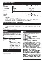
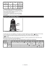
Position of 

speed  

change lever

Speed

Torque

Applicable 

operation

1

Low

High

Heavy load

-

ing operation

2

High

Low

Light loading 

operation

To change the speed, switch off the tool first. Select 

the "2" side for high speed or "1" for low speed but high 

torque. Be sure that the speed change lever is set to the 

correct position before operation.

If the tool speed is coming down extremely during the 

operation with "2", slide the lever to the "1" and restart 

the operation.

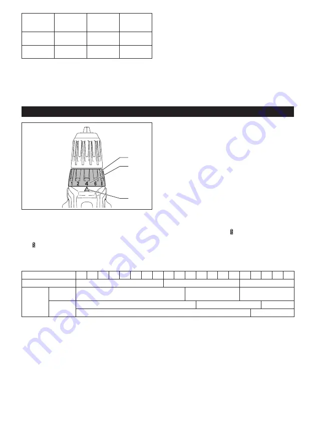
Adjusting the fastening torque

1

2

3

►    

1.

 Adjusting ring 

2.

 Graduation 

3.

 Arrow

The fastening torque can be adjusted in 21 levels by turning the adjusting ring. Align the graduations with the arrow 
on the tool body. You can get the minimum fastening torque at 1 and maximum torque at 

marking.

The clutch will slip at various torque levels when set at the number 1 to 20. The clutch does not work at 

the 

marking.

Before actual operation, drive a trial screw into your material or a piece of duplicate material to determine which 

torque level is required for a particular application. 


The following shows the rough guide of the relationship between the screw size and graduation.

Graduation

1

2

3

4

5

6

7

8

9

10 11 12 13 14 15 16 17 18 19 20

Machine screw

M4

M5

M6

Wood 

screw

Soft wood 

(e.g. pine)

ɸ

3.5 x 22

ɸ

4.1 x 38

Hard wood 

(e.g. lauan)

ɸ

3.5 x 22

ɸ

4.1 x 38

Summary of Contents for DF333DWYE

Page 1: ...INSTRUCTION MANUAL Cordless Driver Drill DF333D DF033D ENGLISH Original instructions Read before use ...

Page 2: ...Directives on Waste Electric and Electronic Equipment and Batteries and Accumulators and Waste Batteries and Accumulators and their implementation in accordance with national laws electric equipment and batteries and battery pack s that have reached the end of their life must be col lected separately and returned to an envi ronmentally compatible recycling facility Intended use The tool is intende...

Page 3: ...nd matching outlets will reduce risk of electric shock 2 Avoid body contact with earthed or grounded surfaces such as pipes radiators ranges and refrigerators There is an increased risk of elec tric shock if your body is earthed or grounded 3 Do not expose power tools to rain or wet con ditions Water entering a power tool will increase the risk of electric shock 4 Do not abuse the cord Never use t...

Page 4: ...ts etc in accordance with these instructions tak ing into account the working conditions and the work to be performed Use of the power tool for operations different from those intended could result in a hazardous situation 8 Keep handles and grasping surfaces dry clean and free from oil and grease Slippery handles and grasping surfaces do not allow for safe handling and control of the tool in unex...

Page 5: ... of your eyesight 5 Do not short the battery cartridge 1 Do not touch the terminals with any con ductive material 2 Avoid storing battery cartridge in a con tainer with other metal objects such as nails coins etc 3 Do not expose battery cartridge to water or rain A battery short can cause a large current flow overheating possible burns and even a breakdown 6 Do not store the tool and battery cartr...

Page 6: ...stall the battery cartridge forcibly If the cartridge does not slide in easily it is not being inserted correctly Battery protection system The tool is equipped with a battery protection system This system automatically cuts off power to the motor to extend battery life The tool will automatically stop during operation if the tool and or battery are placed under one of the following conditions Ove...

Page 7: ...ination Reversing switch action 1 A B 1 Reversing switch lever CAUTION Always check the direction of rotation before operation CAUTION Use the reversing switch only after the tool comes to a complete stop Changing the direction of rotation before the tool stops may dam age the tool CAUTION When not operating the tool always set the reversing switch lever to the neu tral position This tool has a re...

Page 8: ...ng torque can be adjusted in 21 levels by turning the adjusting ring Align the graduations with the arrow on the tool body You can get the minimum fastening torque at 1 and maximum torque at marking The clutch will slip at various torque levels when set at the number 1 to 20 The clutch does not work at the marking Before actual operation drive a trial screw into your material or a piece of duplica...

Page 9: ...ection of the arrow and insert the driver bit into the sleeve as far as it will go Then release the sleeve to secure the driver bit 2 1 1 Driver bit 2 Sleeve To remove the driver bit pull the sleeve in the direction of the arrow and pull the driver bit out NOTE If the driver bit is not inserted deep enough into the sleeve the sleeve will not return to its original position and the driver bit will ...

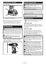
Page 10: ...ameter of the screw It makes driving easier and prevents splitting of the workpiece Drilling operation First turn the adjusting ring so that the arrow points to the marking Then proceed as follows Drilling in wood When drilling in wood the best results are obtained with wood drills equipped with a guide screw The guide screw makes drilling easier by pulling the drill bit into the workpiece Drillin...

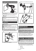
Page 11: ...r and lock it with the hol ster button You can keep two driver bits at the front of the holster MAINTENANCE CAUTION Always be sure that the tool is switched off and the battery cartridge is removed before attempting to perform inspection or maintenance NOTICE Never use gasoline benzine thinner alcohol or the like Discoloration deformation or cracks may result To maintain product SAFETY and RELIABI...

Page 12: ...ms in the list may be included in the tool package as standard accessories They may differ from country to country www makita com Makita Europe N V Makita Corporation 3 11 8 Sumiyoshi cho Anjo Aichi 446 8502 Japan Jan Baptist Vinkstraat 2 3070 Kortenberg Belgium 885672A226 EN 20190329 ...

Reviews: