P
7
/
8
C
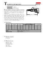
ircuit diagram
How to Check the Switch Condition
1. Unscrew the two screws or disconnect the two receptacles.
(If not, the Switch condition cannot be judged correctly because current flows through Controller.)
2. Check the condition between the terminals (shown below) with a tester (Makita part No. 1R402).
Good condition
Endbell complete
viewed from rear side
Terminal
Receptacles
Insulated terminals
Pan head screws
red
red
yellow
black
Controller
red
red
red
black
Connectors
Line filter
(if used)
red
• Either of the two red lead wires from Terminal and
Controller can be connected to either 1 or 2 .
• Either of the two red lead wires from Terminal and
Controller can be connected to either or .
Switch
Terminals
OFF
O.L (
∞
)
O.L (
∞
)
0.1
Ω or less
0.1
Ω or less
ON
Switch condition
and
and
Fig. D-1