
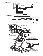

C
ircuit diagram
W
iring diagram
P 9 / 9
Terminal
M1
M2
Controller
Switch
Motor
black
black
black
Orange
Orange
black
red
Brush holder lead wire
(Black)
Brush holder lead wire
(Red)
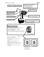
Terminal
M1
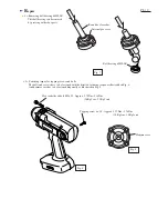
Do not slack the brush holder
lead wire (black )in this portion.
Fix lead wire (red and white)
with lead holder.
Do not pinch lead wire (black ) of
controller between switch holding rib
and switch. See the following illustration
in detail.
Controller
Do not pinch between these
switch holding ribs and switch.
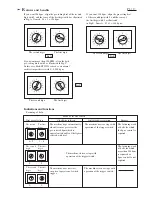
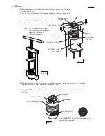
Connecting brush holder lead wire (black) with switch
Connecting brush holder lead wire (black) with switch
Take off the sheath so that
the size of wire portion is
approx. 7mm. And mount
connector to the wire portion.
Bent the lead wire, and
cover the connector and
lead wire with thermoplastic tube.
Connector
Thermoplastic tube
Connect with switch.
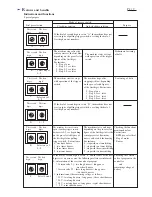
Connecting brush holder lead wire (black) with switch
7mm
Lead wire pinched
with rib and switch


