P 7 / 9
R
epair
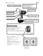
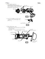
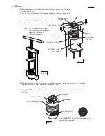
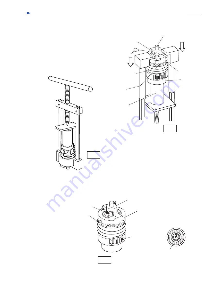
(2)Adjust the opening for steel ball inserting, to the cam groove top of spindle
as illustrated in Fig. 5.
Spindle
Cam groove top
of spindle
Opening for steel
ball inserting
Steel ball 5.6 x 2pcs.
Steel ball 4 x 25pcs.
Hammer
(3)Take off 2 pcs. of steel balls 5.6 with magnetic bar or tweezers from spindle.
(4)Loosen the handle of 1R045 turning it anti-clockwise
and remove hammer from spindle.
(5)When assembling, adjust the "opening for steel ball inserting", to the "cam groove top" of spindle
and insert steel ball 5.6 into hammer as illustrated in Fig. 5.
< Note > Set the hammer as per Fig.5A,
when removing it from spindle.
Otherwise steel balls 4
will fall off hammer.
Ball bearing
6002LLB
1R165 Ring spring
setting tool B
Fig. 5
Fig. 5A
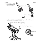
(6) Apply MAKITA grease N No.2 in small volume to the position marked with black triangle mark.
See Fig. 6.
(1) Spindle
(3) Steel ball 5.6 x 2
(2) Steel ball 4 x 25pcs.
Hammer
(4) Spur gear 24
Fig. 6
Bottom view of spindle
Apply MAKITA grease N No.2 in small volume
into the hole of spindle.


