P 5 / 9
R
epair
[3] -1. Disassembling/Assembling Hammering Mechanism (cont.)
Do the reverse of assembling steps.
Note:
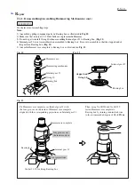
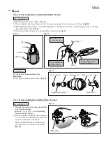
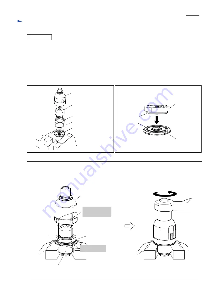
1) Assemble by piling component parts on Bearing box as illustrated in Fig. 10.
2) Make sure that twenty-six 3.5 Steel balls are in place inside Hammer.
3) Do not forget to install O ring 40 when assembling Internal gear 51 to Bearing box. (Fig. 11)
4) Internal gear 51 is not reversible when assembled to Bearing box. Be sure to assemble so that the stepped end of
the gear face Bearing box. (Fig. 11)
5) Assemble Hammer case complete to Bearing box as illustrated in Fig. 12.
Fig. 12
Bearing box
Hammer case complete
Socket 32-50 for fixing Bearing box
four projections
Internal gear 51
ASSEMBLING
Fig. 11
Fig. 10
Internal gear 51
O ring 40
Bearing box
Hammering mechanism
Hammer case
Fit Hammer case complete over Internal gear 51 with
the four grooves on the inside of Hammer case complete
aligned with the corresponding projections on Internal gear 51.
Then, using No.1R224 and No.1R223,
fasten Hammer case complete to
Bearing box by turning counterclockwise
to the recommended torque of 30 - 40 N.m.
four grooves on
the inside surface
Internal gear 51
Bearing box
O ring 40
stepped end


