


P 8/ 9
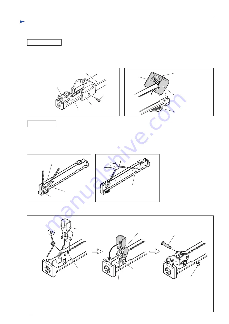
1) Remove M4x10 Pan head screw, and then pull out Sub magazine from Main magazine.
2) Pivot Pusher and Separate it from Tension spring 3 and Sub magazine.
3) Remove Stop ring E-3 from Pin 4. Lever portion can be removed.
Sub magazine
DISASSEMBLING
Main magazine
End cap
Pusher
Adjuster
Adjuster side of
Sub magazine
Lever side of
Sub magazine
notch of Pusher
Tension
spring 3
M4x10
Pan head
screw
[4] DISASSEMBLY/ ASSEMBLY
[4]-6. Magazine section
R
epair
Fig. 27
Fig. 29
Fig. 31
Fig. 30
Fig. 28
1) Pass Tension spring 3 between cylinder portion and bottom of Sub magazine. (Fig. 29)
2) Hook the spring end on Adjuster side with the notch of Pusher . (Fig. 28)
3) Pick up the other spring end using Pincette. And hook the spring end with the hook on the bottom of Sub magazine as
illustrated in Fig. 30.
4) As for Lever portion, assembling the components in accordance with the way illustrated in Fig. 31.
ASSEMBLING
bottom of
Sub magazine
Adjuster
hook on the bottom
of Sub magazine
cylinder portion of Sub magazine
for hooking Tension spring 3
Lever
straight end
Torsion spring
5
Lever
Pin 4
Stop ring E-3
Sub magazine
hook of
Sub magazine
protrusion of
Lever
Straight tail attached to the bottom of
Sub magazine
bend end
Attach the bend end of Torsion spring 5
to the inside of Lever. Then insert Lever
and Torsion spring 5 into Sub magazine.
Move Lever vertical to Sub magazine,
and hook the protrusion of Lever with
the hook of Sub magazine while
compressing Torsion spring 5.
Secure Lever portion in place by
Stop ring E-3 and Pin 4.


