P
7
/ 1
0
R
epair
[3] DISASSEMBLY/ASSEMBLY
[3]-4. Front Base, Base, Foot
DISASSEMBLING
Fig. 11
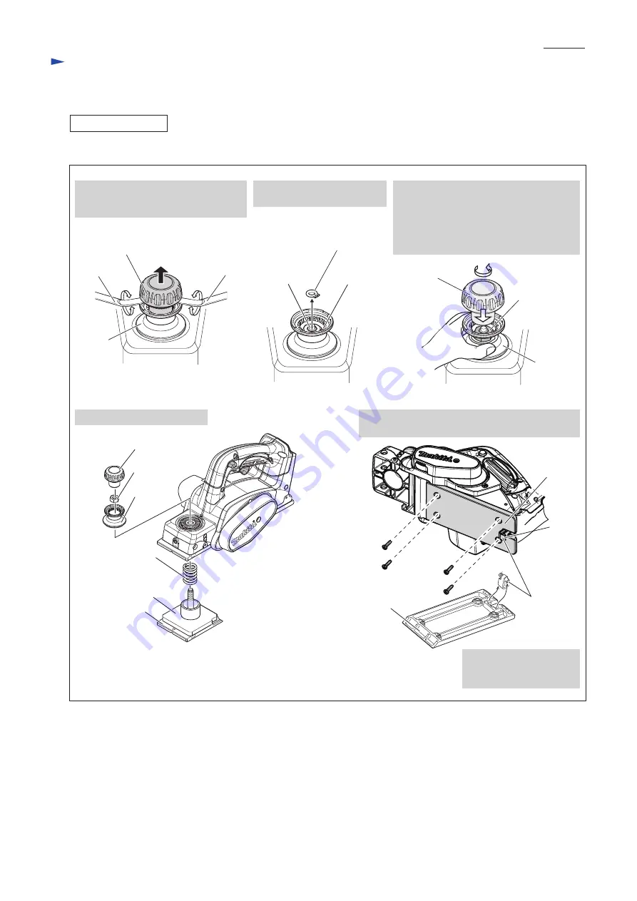
Disassemble Front base and Base (rear side). (
Fig. 11
)
1. Remove Knob cover by levering up
with 1R263 inserted into the gap
between Knob cover and Knob.
4. Front base can be removed.
2. Remove Retaining ring S-8
with 1R004 or 1R291.
3. Use Knob cover as a socket wrench
temporarily for removing M10 Hex nut.
Turn Knob cover
counterclockwise
while holding Knob by hand.
M10 Hex nut can be removed from
the thread of Front base.
5. Remove Base (rear) by unscrewing four 4x18
Tapping screws.
6. Foot can be removed in
separating Base from
Main frame complete.
Knob cover
Retaining Ring S-8
M10 Hex nut
Knob
1R263
1R263
M10 Hex nut
Knob cover
Knob
Front base
Rubber packing
Compression
spring 18
Foot
4x18 Tapping screw (4pcs.)
M10 Hex nut
Thread portion
of Front base
Knob
Knob cover
Foot
Base (rear)
Base (rear)


