background image

4

/ 1

0

R

epair

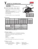
[3] DISASSEMBLY/ASSEMBLY

[3]-2. Motor section

DISASSEMBLING

(1) Remove Poly V-belt 4-241.   (Refer to 

Fig. 2

)

(2) Separate Bracket section from Main frame complete.   (

Fig. 5

)

Fig. 5

Fig. 6

1. Remove Carbon brushes. 2. Remove four 4x18 Tapping screws. 3. Remove Bracket by tapping Main frame

    complete with Plastic hammer. Armature

    and Drum complete come with Bracket. 

Carbon brush

Carbon brush

Main frame

complete

4x18 Tapping screw

(4 pcs.)

5. Hold Armature by gloved hand, 

    engage 12.7mm Square side to 

    Square portion of V-pulley 4-24L

    and Remove V-pulley by turning


clockwise

.

6. Remove Armature from Bracket

    by tapping Armature shaft with

    Plastic hammer.

7. Remove Ball bearings

    of both side of Armature

    with 1R269.

Impact 

driver

Phillips bit 

Bit adapter

 (P/N:A-33750 or P/N:134873-0)

4. Set Phillips bit and Bit adapter

    (P/N:A-33750 or P/N:134873-0)

    to Impact driver for removing 

    V-pulley.

12.7mm 

     Square side

V-pulley 4-24L

Armature

(3) Disassemble Armature from Bracket.  And remove Ball bearings.    (

Fig. 6

)

Armature

Bracket

Ball bearings

Caution: 

Do not pinch your finger in this step. 

                 Armature tends to be strongly pulled 

                 back into Main frame complete due to 

                 the strong magnet force toward Yoke unit.

Summary of Contents for BKP180RF

Page 1: ...ade 1 Blade gauge assembly 1 Socket wrench 9 1 Guide rule 1 Dust nozzle 1 Plastic carrying case except for BKP180Z LXPK01Z 1 1 Planer blade re sharpenable type disposable type Guide rule Blade gauge assembly Dust nozzle Dressing stone Elbow Fast charger DC18RA Charger DC18SD Automotive charger DC18SE Charger DC24SC Li ion battery BL1830 Dust bag Specification 14 000 Yes 3 4 7 4 No load speed rpm m...

Page 2: ...ing ring S R pliers 1R269 Baring extractor small removing Ball bearings 1R263 Baring extractor removing Knob cover Item No Description Lubricant VG100 a little Amount Portion to lubricate Knob cover Knob Main Frame Rubber packing 24 24 Front base 17 Makita grease N No 2 17 Cam plate b Cylindrical portion where Main frame contacts a Threaded portion Surface where Knob contacts Apply the following l...

Page 3: ... cover Disassemble Poly V belt 4 241 Fig 2 Assemble Poly V belt 4 241 Figs 3 and 4 ASSEMBLING Fig 3 Fig 4 V pulley 4 24L on Motor side 1 Hook Poly V belt 4 241 with V pulley 4 24L 3 Turn V pulleys 4 24L and 4 33 5 counterclockwise by hands to fit Poly V belt 4 241 to V pulleys while holding Poly V belt firmly 2 Hook a part of Poly V belt 4 241 with V pulley 4 33 5 If it is difficult to completely ...

Page 4: ...o Square portion of V pulley 4 24L and Remove V pulley by turning clockwise 6 Remove Armature from Bracket by tapping Armature shaft with Plastic hammer 7 Remove Ball bearings of both side of Armature with 1R269 Impact driver Phillips bit Bit adapter P N A 33750 or P N 134873 0 4 Set Phillips bit and Bit adapter P N A 33750 or P N 134873 0 to Impact driver for removing V pulley 12 7mm Square side ...

Page 5: ...mble Armature to Bracket and set V pulley 4 24L to Armature by taking the disassembling step in reverse Refer to Fig 6 Note in Assembling 1 Tighten V pulley 4 24L to Armature shaft by turning it counterclockwise 2 It is not necessary to tighten V pulley 4 24L to very high torque Reaction torque caused by stopping the rotation prevents V pulley 4 24L from being loose 3 further assemble by taking th...

Page 6: ...old Drum by hand engage Bit adapter to Square portion of V pulley 4 33 5 and Remove V pulley by turning it counterclockwise 4 The clearance between Ball bearing 608ZZ and Drum is too small to insert the jaws of 1R269 Therefore sharpen the jaws Ball bearing 608ZZ Drum 5 Insert the jaws of 1R269 into the clearance between Ball bearing 608ZZ and Drum and fix the jaws of 1R269 in Vise And then remove ...

Page 7: ...t wrench temporarily for removing M10 Hex nut Turn Knob cover counterclockwise while holding Knob by hand M10 Hex nut can be removed from the thread of Front base 5 Remove Base rear by unscrewing four 4x18 Tapping screws 6 Foot can be removed in separating Base from Main frame complete Knob cover Retaining Ring S 8 M10 Hex nut Knob 1R263 1R263 M10 Hex nut Knob cover Knob Front base Rubber packing ...

Page 8: ...faces of Front base and Base contact the rule completely Planing depth will be set at the zero level by the above adjustment Base Base 1 Pass Long pin of Foot through Torsion spring 7 2 Facing Torsion spring 7 side to the opposite side of Belt cover side assemble Foot to Base rear with putting Torsion spring s tail on the Base Foot Torsion spring 7 Long pin of Foot Belt cover side Belt cover side ...

Page 9: ...er s Lead wires put them into Lead wire holders Motor housing viewed from Rear cover side Motor housing viewed from Bracket side Brush holder A Line filter Motor Housing Controller Terminal AS Switch Wiring of Brush Holder s Lead Wire 1 Tightening Brush Holder s Lead Wires and put them in Lead wire holders And guide them to inside of Motor housing through the opening Brush holder B Brush holder B ...

Page 10: ...roller Terminal Switch Wiring in Main frame Put Lead wires into Lead wire holders Slack Lead wires for connecting to Switch have to be put in this portion First put Controller s lead wires into Lead wire holder And then put Field lead wires red black on Controller s lead wires when fixing them with this Lead wire holder Place Field lead wires in this Lead wire holder when setting Line filter to Mo...

Reviews: