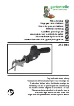
background image

P 6 /14

R

epair

Fig. 13

DISASSEMBLING

[3] -3. Slider Section

Insulation cover

LED circuit

Gear housing
cover complete

1) After removing Shoe, then Insulation cover. (Fig. 13)
2) Remove the Blade clamp section. (See "[3] -1. Blade Clamp Section.)

3) Remove Cover from LED circuit, then disconnect the
    connector from the connector of Power supply unit.
   (Fig. 14)
4) Remove LED circuit from Gear housing cover
    complete by lifting up as illustrated in Fig. 15,
5) Remove Gear housing cover complete from Gear
    housing complete by unscrewing four M5x25
    Pan head screws. (Fig. 16)

Insulation cover

Slider, after removal of
the Blade clamp section

Gear housing
complete

Gear housing
cover complete

Fig. 15

Fig. 16

Pan head screw 

M5x25 (4pcs)

For smooth removal of Insulation cover,
apply soapy water into the slit between
Insulation cover and Gear housing cover
complete. 
Important: Be careful not to wet
LED circuit with soapy water.

Fig. 14

Cover

Connector of
Power supply unit

LED circuit

Gear housing
cover complete

Summary of Contents for BJR181

Page 1: ...ess Recipro Saw Recipro saw blade for wood 1 pc Recipro saw blade for metal 1 pc Charger DC18SC Charger DC24SA Charger DC24SC Li ion battery BL1830 Assorted recipro saw blades Battery Electric brake M...

Page 2: ...40 Flat washer 14 Surface that contacts Gear assembly Plane bearing 14A 17 X ring 14 Inside surface that contacts Slider complete 46 Gear housing complete Pin 10 the gear shaft for Gear assembly Gear...

Page 3: ...Compression spring 6 Driving sleeve guide Pin 3 of 6mm length Guide sleeve Sleeve Protector Retaining ring S 18 4 While putting your finger on the top of Slider to close the slit of Slider remove Pin...

Page 4: ...that Push plate is not reversible when installed While pushing Push plate straight into Slider with recipro saw blade insert Pin 3 of 19 8mm length through the hole of Push plate as illustrated to ri...

Page 5: ...Then cover Driving sleeve with Protector When installing Driving sleeve fit its projections in the concavities of Sleeve and Driving sleeve guide Projections Concavities Driving sleeve Driving sleeve...

Page 6: ...ete by lifting up as illustrated in Fig 15 5 Remove Gear housing cover complete from Gear housing complete by unscrewing four M5x25 Pan head screws Fig 16 Insulation cover Slider after removal of the...

Page 7: ...Motor housing side 6 Remove two Plates from Gear housing cover complete by unscrewing four M5x16 Pan head screws Fig 17 Note It is recommended to use impact driver to remove the screws because they ar...

Page 8: ...ar housing cover complete from the Blade clamp side then put Oil seal 14 onto X ring 14 Note Oil seal 14 is not reversible when assembled to Gear housing complete Be sure to assemble so that the lip p...

Page 9: ...ar housing complete Fig 24 Gear assembly Needle bearing 708 Needle bearing 1012 Flat washer 14 Gear housing complete Plate C Torx socket head screw M5x14 No 1R314 Gear assembly Needle bearing 708 Need...

Page 10: ...g 27 Pan head screw M5x16 Do the reverse of the disassembling steps Note Make sure that Stop ring E 10 is assembled in place on Armature shaft to secure Ball bearing 6001DDW Fig 28 Bearing retainer 63...

Page 11: ...off button to the Handle section do as illustrated in Fig 30 Handle R Handle L Lock off button Leaf spring Be sure to remove Hook assembly before disassembling the handle section because this portion...

Page 12: ...ires sheath Black White Red Orange Blue Left view Left view Switch Heatsink Right view Brush holder Left Brush holder Right Power supply circuit FET Protective tube Right view LED circuit Brush holder...

Page 13: ...from Power supply circuit to Connector Lead wire blue from Switch to Connector Be careful not to route lead wire blue over this rib With this lead wire holder fix the following lead wires from Power s...

Page 14: ...ow rib A rib B 2 Motor Section 3 LED Circuit Motor housing viewed from front Route the two Lead wires black white of Power supply circuit as illustrated below Connector of Power supply circuit Motor h...

Reviews: