


P 10/ 13
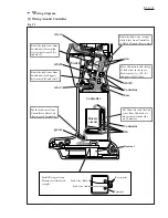
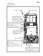
Fig. 28
C
ircuit diagram
Stator
Controller
Terminal
Main switch
Switch unit B
(for rotation
reverse)
Switch unit A
(for Trigger)
Switch unit C
(for clutch)
LED
circuit
(for job
light)
LED PWB
(for display)
Buzzer
circuit
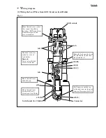
Color index of lead wires' sheath
Black
White
Red
Orange
Blue
Yellow
= Tape
= Connector
Motor control unit


