


P 14/15
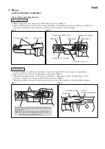
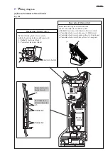
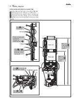
Fig. D-3
W
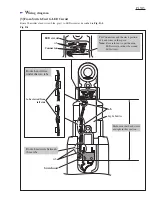
iring diagram
[2] From Main Switch to Switch Unit
Yoke unit
Gear case
Switch unit
Main switch
rib
Route the following Lead wires as described in Fig. D-3.
Controller's lead wires (blue, gray) to LED circuit
Controller's lead wires (purple, yellow) to Switch unit
Switch unit's lead wires (purple, yellow) to Controller
Endbell's lead wires (red and black) to Reverse switch
Connector
rib
Put the following parts
in this space:
Connectors
Slack portion of
Route under
Switch unit.
Route and
between the rib and
the inside wall of
Housing R.
Endbell complete
Route and
between these ribs.
rib
Route between this rib
and Endbell complete.
Make sure that
Lead wires
are tight in this
portion.
Make sure that
Lead wires
are tight in this
portion.