


P 13/15
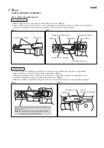
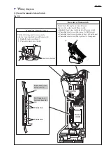
Fig. D-2
W
iring diagram
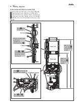
[1] From Terminal to Main Switch
Route the following Lead wires between
the two ribs on the rear of Main switch:
Endbell's lead wires (red, black) to Reverse switch
Controller's lead wires (blue, gray) to LED circuit
Controller's lead wires (purple, yellow) to Switch unit
Controller's lead wires (blue, yellow) to Lamp unit
Right side of Main switch
1
2
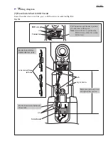
Lead wire holder
Fix the following Lead wires securely
with the Lead wire holders on Main switch:
1. Endbell's lead wire (black)
2. Controller's lead wire (white)
Rear side of Main switch
rib
rib
Route Lead wires
beside this rib.
Put Connectors
between these ribs.
Controller
Buzzer
circuit
Terminal
Connector
Connector
rib
Main switch