background image

0

Readjusting the line of the 2-line trimmer head

The line length can be adjusted at any time with the best possible 

results by tapping the line trimmer head on the ground lightly 

during the mowing operation. The lengthening of the line amounts 

to approx. 40 mm for each releasing operation.
The line blade cuts off projecting ends of the line automati-

cally.

Checking/replacing the line of the 2-line trimmer head

The new nylon line must be four meters long and have a dia-

meter of Ø 3.0 mm (order number, see extract from the spare 

parts list).
To replace the line, it is advisable to dismantle the line trimmer 

head first (see instructions from section "Installing the 2-line 

trimmer head" in chapter "Preparations" in reverse order).
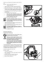
  1  Press in the cover mounting clips and open the line trim-

mer head carefully (Caution! Inner spring presses the two 

housing parts apart) (A).

  2  Take the reel including the line out of the housing (B).
  3  Remove remaining old pieces of line from the reel.

  If there is still sufficient line on the reel, but if the 

line does not adjust itself to the correct length 

during the mowing operation, the line must be 

wound up onto the reel again.

  4  Use a paintbrush to clean the reel bottom side and the 

housing and check for any signs of damage.

  5  Kink the new line in the middle and insert into the partition 

of the two reel guides as shown in the illustration (C, D).

  6  Wind the line from the two reel guides in the direction of 

the arrow tautly onto   the reel (E).

  7  Clamp both ends of the lines in two opposite grooves of the 

reel so that the  

line does not slacken when the reel 

is inserted into the housing (F).

  8  Reinsert the reel into the bottom part of the housing and 

thread both ends of the line into the line guides in the housing 

(G).

  9  Line up the reel according to the cut-outs in the top part of 

the housing and  

press into the housing forcefully until 

both snap-fit closures snap into place   (H).

  Uneven line lengths are cut off by the line blade 

on the cutter guard automatically during regular 

operation.

B

A

D

C

F

E

H

G

Summary of Contents for BCX3400

Page 1: ...e manufacturing plant without being filled with engine oil Fill with engine oil according to instructions before putting the brushcutter into operation Putting the brushcutter into operation without engine oil will result in engine damage immediately BCX3410 BCX3400 ...

Page 2: ...pment 4 Handling fuels refueling the brushcutter 4 Putting into operation 5 Kickback blade thrust 6 Working behavior and working techniques 6 Applications for cutting tools 7 2 line trimmer head 7 4 tooth star blade 7 Transport 7 Storage 7 Maintenance 8 First aid 8 EU Declaration of Conformity 8 Scope of delivery 9 Packaging 9 Main components of the brushcutter 10 Preparations 11 Installing the ha...

Page 3: ...tion Start engine Stop engine ON OFF First aid Recycling Sign CE General safety precautions To ensure correct operation the user has to read this instruction manual to make himself familiar withthehandlingofthebrushcutter Insufficiently informed users will risk danger to themselves as well as others due to improper handling It is recommended only to lend the brushcutter to people who have experien...

Page 4: ...tial that a long pair of trousers made of tough material be worn during operation of the brushcutter Do not wear short pants Protective gloves 6 made of thick leather are part of the prescribed equipment and must always be worn during operation of the brushcutter Safety shoes or boots 7 fitted with anti skid sole steel toe caps and leg protection must always be used Safety shoes equipped with a pr...

Page 5: ...or the above mentioned uses they are intended for as specified in the documentation Startthebrushcutteronlyaftercompleteassembly and inspection Operation of the machine is only permitted after all the appropriate accessories are attached The cutting tool must be equipped with its appro priate cutter guard Never run the cutter without this cutter guard The cutting tool must not turn during idling I...

Page 6: ...shcutter will be thrown to one side at high speed and with great force high risk of injury To avoid kickbacks observe the following Clearthecuttingareaofanyforeignobjectsandpayattention to any existing planted areas and other objects The cutting tool must be turning at full speed before you begin to cut An increased risk of injury exists in the darkly marked area and especially when metal cutting ...

Page 7: ...the brushcutter with the cutting tool still running The transport safety device included in the scope of delivery must always be fitted whenever the brushcutter is being transported over longer distances When transporting the brushcutter in the vehicle make sure that the brushcutter is safely secured Empty the fuel tank before transporting the brushcutter Before shipping the brushcutter completely...

Page 8: ...en Observe the accident prevention instructions issued by the relevant trade associations and insurance companies Do not make any modifications to the brushcut ter You will only be putting your own safety at risk The performance of maintenance or repair work by the user is limited to those activities described in this instruction ma nual All other work must be done by the MAKITA customer service c...

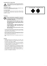
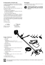
Page 9: ... back intorawmaterial recyclingsystems waste paper utilization EU Declaration of Conformity The undersigned Shigeharu Kominami and Rainer Bergfeld as authorized by DOLMAR GmbH declare that the brushcutters of the make MAKITA Type 366 BCX3410 and BCX3400 conforms to the basic safety and health requirements of the applicable EU directives EU Machinery Directive 98 37 EC EU EMC Directive 89 336 EEC m...

Page 10: ...throttle lever lockout 11 Handle right 12 Short circuit switch Start Stop 13 Throttle lever 14 Handle left 15 Model designation 16 Main tube 17 Cutter guard 18 Angular gearbox 19 4 tooth star blade cutting tool 20 Handle fastening cap 21 Strap holder 22 Foot 23 2 line trimmer head cutting tool 24 Hip protection pad for BCX3410 not included 25 Shoulder strap Year of manufacture Serial number Please...

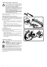
Page 11: ...handle mount 2 Insert the handle as shown in the illustration 3 Place the second anti slip insert 3 on the handle 2 so that it also lines up flush with the handle mount 4 Place the handle fastening cap 4 on top and hold it firm ly 5 Insert the nuts 5 from underneath into the drilled holes of thehandlemount holdtheminplaceandtightenthescrews firmly 6 at the same time do not forget the washers C han...

Page 12: ...end the protective strip slightly with the line blade on the inside and insert into the mounts on the bottom edge of the cutter guard until the snap fit closures snap into place on both sides Installing the cutter guard To install the cutter guard lay down the brushcutter so that it is resting on its handle in stable position 1 Insert the four nuts 1 from the side into the provided cut outs 2 in t...

Page 13: ... plastic locking device and must be replaced for safety reasons with a new fastening nut immediately in the case of noticeable easy movement but no later than after the tool has been changed 10 times see extract from the spare parts list 6 Remove the assembly pin again and check the cutting tool for free movement 2 line trimmer head To install the cutting tool lay down the brushcutter so that it i...

Page 14: ...de a physician must be consulted immediately Gasoline The engine of the brushcutter is designed to be run with regular gasoline with a minimum octane number of 91 RON If that type of fuel is not available fuel with a higher octane number can also be filled into the tank without damaging the engine Engine oil Theengineislubricatedexclusivelybytheengineoil multigrade oiloftheclassificationSAE10W 30 ...

Page 15: ... at the height of your hip bone TheshoulderstrapsoftheBCX3410brushcutters are not equipped with a hip protection pad Balancing the brushcutter To balance the brushcutter the machine must have been re fueled and filled with oil see section Refueling the brushcutter in this chapter The ground clearance depends on the selected cutting tool When a line trimmer head is being used on level ground the li...

Page 16: ...ropriate cutter guard Never operate the machine without the cutter guard In the case of noticeable changes in the behavior of the machine turn off the engine immediate ly If the cutting tool comes into contact with stones or other hard objects turn off the engine imme diately and check the cutting tool Checking the reliable operating condition of the brushcutter Before starting the brushcutter alw...

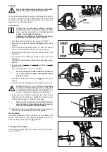
Page 17: ...r quickly and forcefully until the first audi ble ignition occurs The engine will start to run for a short time Do not pull out the starter handle more than 50 cm and do not let it fly back instead guide it back slowly by hand 7 Move the choke lever 2 downward into position open choke 8 Pull the starter handle again until the engine starts to run At idle throttle lever 6 is not operated the cuttin...

Page 18: ...t medium speed At idle the cutting tool must no longer rotate If the cutting tool is rotating the idle speed must be readjusted The tool you will require is the Phillips screwdriver To adjust the idle speed 1 Proper cutting tool must be installed 2 Let the engine warm up 3 Release the throttle lever 1 4 If necessary readjust the idle speed by regulating the idle screw 2 Turn the screw inward for f...

Page 19: ... down 2 Clean the area around the dipstick 1 thoroughly so that no dirt can get into the crankcase 3 Lay down the brushcutter so that it is resting on its foot in stable position 4 Turn the dipstick out of the opening anticlockwise 5 Wipe off the dipstick with a clean rag 6 Dip the dipstick through the opening into the crankcase and pull it out again 7 Read the oil level see illustration 8 If nece...

Page 20: ...ng B 3 Remove remaining old pieces of line from the reel If there is still sufficient line on the reel but if the line does not adjust itself to the correct length during the mowing operation the line must be wound up onto the reel again 4 Use a paintbrush to clean the reel bottom side and the housing and check for any signs of damage 5 Kink the new line in the middle and insert into the partition...

Page 21: ... Place the air filter cover on the upper clips 6 first and then press the lower part of the cover in the direction of the engine you must be able to hear the cover snap into place 8 Retighten the screw firmly Weekly maintenance The following maintenance work must be carried out once a week during regular use Checking replacing the spark plug The engine must have cooled down completely before you c...

Page 22: ...Do not lubricate the angular gearbox with grease on your own The angular gearbox must be lu bricated with grease in one of the many MAKITA service centers The lubrication can be precisely dosed in a workshop This ensures that excessive amounts of grease do not cause over heating in the angular gearbox Changing the engine oil Following first time operation of the brushcutter the engine oil must be ...

Page 23: ...om edge of the filler opening 3 An engine oil bottle can be used for precise do sing without spilling engine oil see extract from the spare parts list 9 Turn the dipstick back in again Quarterly maintenance Suction head in the fuel tank Preventcontactoftheskinwithfuels Weargloves during the maintenance procedure Mineral oil products degrease the skin In case of repeated longer contact the skin wil...

Page 24: ...er Safety locking button Start Stop switch Air filter Cooling air guide Cutting tool Idle speed Engine oil Gasoline hoses Spark plug Muffler Suction head Gasoline tank Fuel tank Carburetor Complete brushcutter Gasoline hoses Valve play Check for damage and sealed tightness Check for proper function and firm fit Check for proper function Check for proper function Check for proper function Clean Cle...

Page 25: ...ne and guarantee the highest quality in material dimensions functioning and safety Original spare parts and accessories can be obtained from your local dealer He will also have the spare part lists to determine therequiredsparepartnumbers andwillbeconstantlyinformed about the latest improvements and innovations regarding the spare parts being offered Please note also that if non original MAKITApar...

Page 26: ...l up see chapter Maintenance Spring in the starter broken broken parts inside the engine service case Carburetor soiled service case Idle setting not correct see chapter Operation Suction head soiled see chapter Mainte nance Carburetor soiled service case Tank vent defective fuel line interrupted cable or Start Stop switch defective service case Air filter soiled see chapter Maintenance Carburetor...

Page 27: ...eed 3 5 5 4 m s2 left handle idle maximum speed 2 0 5 4 m s2 Vibration acceleration ah w according to ISO 79164 BCX3410 front handle idle maximum speed 2 1 7 7 m s2 rear handle idle maximum speed 2 5 11 8 m s2 Fuel consumption according to ISO 88933 0 458 kg h Specific consumption according to ISO 88933 426 g kWh Capacity of the fuel tank 0 65 l Fuel Regular gasoline Engine oil SAE 10W 30 classifi...

Page 28: ...Makita Werkzeug GmbH Postfach 70 04 20 D 22004 Hamburg Germany Subject to alterations Form 995 707 508 8 06 GB ...

Reviews: