background image

8

/ 1

4

R

epair

[4] DISASSEMBLY/ASSEMBLY
[4]-4. Trigger assembly (cont.)

ASSEMBLING

Torsion spring 6

wide hook

Torsion spring 6

Torsion spring 6

Hook the narrow hook of Torsion spring 6
between two protrusions of Stopper plate.

Hook the wide hook of Torsion
spring 6 with Stopper plate as
illustrated.

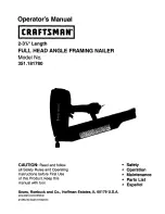
(1)  Set the following parts in place as illustrated in Fig. 17.
       Torsion spring 5       Stopper plate       Torsion spring 6       Lever

Torsion spring 5

Torsion spring 5

Torsion Spring 5

Hook the one of tail of  
Torsion spring 5 on the
protrusion of Stopper plate.

Lever

stopper plate

Face the wide hook of Torsion spring 6 to Lever.
Match the arch ends of Stopper plate and Lever to
make a cylinder for Torsion spring 6.

narrow hook

arch ends of Stopper plate

arch ends of Lever

Lever

Fig. 17

Lever

Setting Lever (for single firing) together with Stopper plate
to Trigger base, pass Pin 3 through them.

Lever has to be set under Trip lever 
as illustrated below.  

Trip lever 

Trigger

Fig. 18

Trigger base

Trigger base

Pin 3

Lever

Stopper plate

Fix the other Tail of Torsion 
spring 5 with the protrusion
of Trigger base.

The other tail of
Torsion spring 5

(2)  Mount the above part to Trigger base. (Fig. 18

(3) Assemble the Trigger base section to Housing set. (Figs. 1514 and 12

protrusion of
Trigger base

Summary of Contents for AN250HC

Page 1: ...ose adapter A 2 Nose adapter B 2 Plastic carrying case 1 Optional accessories Plastic sheet collated concrete pins Air hoses etc Air leak repair set Specification Nail collation angle 0 degree 2 5 0 0...

Page 2: ...m to Trigger base section 1R291 Retaining ring S and R pliers Removing installing Retaining ring R 24 Item No Apply Isoflex NB52 to the following portions to protect parts and product from unusual abr...

Page 3: ...head bolt M8x30 Hex socket head bolt Torque N m Q ty Use for 1 4 4 Inlet cap 1 37 One touch joint H22PM 1 63 M5x22 Pan head screw 1 32 M5x30 Hex socket head bolt 1 42 M4x10 Hex socket head bolt 1 93 M...

Page 4: ...emains in Top cap Filter Head valve Head valve guide Remove Head valve O ring 6 Remove Top cap gasket and O ring 6 Do not lose O ring 6 Rear cushion Top cap complete Air duster While filling one of tw...

Page 5: ...llustrated in Fig 7 1 Driver and Cylinder section can be removed as illustrated in Fig 6 3 O rings of Cylinder section can be replaced as illustrated in Fig 8 Take the disassembling step in reverse Re...

Page 6: ...securing Trigger assembly Trigger valve stem Trigger valve section Trigger assembly Adjuster assy Change rod Pliers Remove Trigger assembly and Change rod from Housing set Remove the following Spring...

Page 7: ...2 in places Fig 14 Fig 14 Fig 13 step of 1R268 for receiving 3mm Spring pin 1R268 Spring pin 3 20 Spring pin 3 32 3pcs Spring pins 3 20 3 32 DISASSEMBLING 4 4 Trigger assembly 1 Remove Contact arm and...

Page 8: ...plate Lever stopper plate Face the wide hook of Torsion spring 6 to Lever Match the arch ends of Stopper plate and Lever to make a cylinder for Torsion spring 6 narrow hook arch ends of Stopper plate...

Page 9: ...assy can be disassembled without removing Spring pins around Trigger assembly and Trigger valve section Slide plate Turn Adjuster piece 90 left in Upper yoke as illustrated below Adjuster piece can be...

Page 10: ...as illustrated in Fig 21 3 Disassemble Door from Driver guide as illustrated in Fig 22 Fig 21 Fig 22 ASSEMBLING DISASSEMBLING DISASSEMBLING Front cushion M8x30 Hex socket head bolt 4pcs Remove four M8...

Page 11: ...ove Retaining ring R 24 while holding Cup washer with your finger Because Cup washer is slung by Compression spring 9 and Compression spring 10 Now the following parts are disassembled from Driver gui...

Page 12: ...ver guide mount Compression spring 3 to the elliptic hole of Feeding claw While pressing Compression spring 3 with slotted screwdriver insert Piston into Driver guide And push Piston to the position w...

Page 13: ...ete Magazine cap complete can be separated from Magazine as illustrated below M5x20 Hex socket head bolt Take the disassembling step in reverse ASSEMBLING Take the disassembling step in reverse 4 9 Do...

Page 14: ...ated in Fig 29 If it is difficult to remove One touch joint H22PM as illustrated in Fig 29 One touch joint can be disassembled as illustrated in Fig 29A Note One touch joint H22PM and Inlet cap as Mak...

Reviews: