12 ENGLISH
Optional rubber attachments
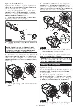
Optional rubber attachments require to be placed over
the nozzle. Be careful not to attach rubber attachments
directly to the air vent hose complete.
i
Align the guide projections on the nozzle 13 with
the locking notches on the lock sleeve of the air vent
hose complete, then push the nozzle firmly into the lock
sleeve until it locks in place with a click.
ii
Place a rubber attachment over the nozzle head
by pushing and hand screwing it in place.
1
1
2
3
Fig.11
►
1.
Rubber attachments
2.
Nozzle 13
3.
Air vent hose
complete
NOTICE:
Make sure that the nozzle has been
correctly attached to the air vent hose complete
so the guide projections on the nozzle neatly fit
into the locking notches on the lock sleeve.
2.
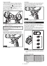
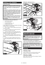
Turn the dust cap on the suction inlet at the rear of
the housing counterclockwise to take the dust cap out
of the housing. Two locking tabs on the dust cap can be
disengaged by aligning them with the guide grooves on
the housing.
1
2
3
4
Fig.12
►
1.
Dust cap
2.
Locking tabs
3.
Suction inlet
4.
Guide
grooves
3.
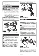
Attach the end of the air vent hose complete to
the suction inlet, aligning the two locking tabs on the
air vent hose complete with the guide grooves on the
housing. Then hold and turn the rear cuffs of the air vent
hose complete clockwise to secure it in place.
1
4
5
3
2
Fig.13
►
1.
Air vent hose complete
2.
Rear cuffs
3.
Suction
inlet
4.
Locking tabs
5.
Guide grooves
4.
To remove the deflating nozzle and attachments,
follow the installation steps in reverse.
NOTICE:
Always hold and turn the rear cuffs of
the air vent hose complete to install and uninstall
the air vent hose complete in place.
Installing optional filter
Optional accessory
An optional high performance filter (Filter C) is available
for restricting dust intake into the motor under dusty
working conditions.
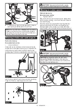
1.
Turn the dust cap on the suction inlet at the rear of
the housing counterclockwise to take the dust cap out of the
housing. Two locking tabs on the dust cap can be disengaged
by aligning them with the guide grooves on the housing.
1
2
3
4
Fig.14
►
1.
Dust cap
2.
Locking tabs
3.
Suction inlet
4.
Guide grooves


