background image

7 ENGLISH

NOTE:

 Wait more than one second before restarting 

the tool when unintentional restart proof functions.

NOTE:

 When the tool is overloaded and the tool 

temperature reaches a certain level, the tool may 

automatically stop. In this situation, let the cool before 

turning on the tool again.

Soft start feature

Soft start feature reduces starting reaction.

ASSEMBLY

CAUTION:


Always be sure that the tool is 

switched off and unplugged before carrying out 

any work on the tool.

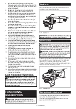
Installing side grip (handle)

CAUTION:


Always be sure that the side grip is 

installed securely before operation.

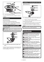
Screw the side grip securely on the position of the tool 

as shown in the figure.

Installing or removing wheel guard (For 

depressed center wheel, flap disc, flex 

wheel, wire wheel brush / abrasive cut-

off wheel, diamond wheel)

WARNING:


When using a depressed center 

wheel, flap disc, flex wheel or wire wheel brush, 

the wheel guard must be fitted on the tool so that 

the closed side of the guard always points toward 

the operator.

WARNING:


When using an abrasive cut-off 

/ diamond wheel, be sure to use only the special 

wheel guard designed for use with cut-off wheels.

(In some European countries, when using a diamond 

wheel, the ordinary guard can be used. Follow the 

regulations in your country.)

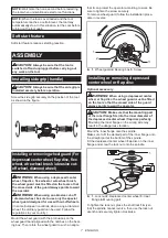
Mount the wheel guard with the protrusions on the 

wheel guard band aligned with the notches on the bear-

ing box. Then rotate the wheel guard to such an angle 

that it can protect the operator according to work. Be 

sure to tighten the screw securely.

To remove wheel guard, follow the installation proce-

dure in reverse.

1

2

3

►    

1.

 Wheel guard 

2.

 Bearing box 

3.

 Screw

Installing or removing depressed 

center wheel or flap disc

Optional accessory

WARNING:


When using a depressed center 

wheel or flap disc, the wheel guard must be fitted 

on the tool so that the closed side of the guard 

always points toward the operator.

CAUTION:


Make sure that the mounting part 

of the inner flange fits into the inner diameter of 

the depressed center wheel / flap disc perfectly.


Mounting the inner flange on the wrong side may 

result in the dangerous vibration.

Mount the inner flange onto the spindle.

Make sure to fit the dented part of the inner flange onto 

the straight part at the bottom of the spindle.

Fit the depressed center wheel / flap disc on the inner 

flange and screw the lock nut onto the spindle.

1

2

4

3

►    

1.

 Lock nut 

2.

 Depressed center wheel 

3.

 Inner 

flange 

4.

 Mounting part

To tighten the lock nut, press the shaft lock firmly so 

that the spindle cannot revolve, then use the lock nut 

wrench and securely tighten clockwise.

Summary of Contents for 9558NBR

Page 1: ...INSTRUCTION MANUAL Angle Grinder 9557NBR 9558NBR ENGLISH Original instructions DOUBLE INSULATION Read before use ...

Page 2: ... earth wire Noise The typical A weighted noise level determined accord ing to EN60745 Sound pressure level LpA 86 dB A Sound power level LWA 97 dB A Uncertainty K 3 dB A WARNING Wear ear protection Vibration The vibration total value tri axial vector sum deter mined according to EN60745 Model 9557NBR Work mode surface grinding Vibration emission ah AG 7 5 m s 2 Uncertainty K 1 5 m s 2 Work mode di...

Page 3: ...t device RCD protected supply Use of an RCD reduces the risk of electric shock 7 Use of power supply via an RCD with a rated residual current of 30 mA or less is always recommended Personal Safety 1 Stay alert watch what you are doing and use common sense when operating a power tool Do not use a power tool while you are tired or under the influence of drugs alcohol or med ication A moment of inatt...

Page 4: ...d wires If power tool or accessory is dropped inspect for damage or install an undamaged accessory After inspect ing and installing an accessory position your self and bystanders away from the plane of the rotating accessory and run the power tool at maximum no load speed for one minute Damaged accessories will normally break apart during this test time 8 Wear personal protective equipment Dependi...

Page 5: ...r tools Wheel intended for larger power tool is not suitable for the higher speed of a smaller tool and may burst Additional Safety Warnings Specific for Abrasive Cutting Off Operations 1 Do not jam the cut off wheel or apply exces sive pressure Do not attempt to make an excessive depth of cut Overstressing the wheel increases the loading and susceptibility to twisting or binding of the wheel in t...

Page 6: ...by domestic regulation 18 Cutting discs must not be subjected to any lateral pressure 19 Do not use cloth work gloves during operation Fibers from cloth gloves may enter the tool which causes tool breakage SAVE THESE INSTRUCTIONS WARNING DO NOT let comfort or familiarity with product gained from repeated use replace strict adherence to safety rules for the subject product MISUSE or failure to foll...

Page 7: ...ond wheel the ordinary guard can be used Follow the regulations in your country Mount the wheel guard with the protrusions on the wheel guard band aligned with the notches on the bear ing box Then rotate the wheel guard to such an angle that it can protect the operator according to work Be sure to tighten the screw securely To remove wheel guard follow the installation proce dure in reverse 1 2 3 ...

Page 8: ...ng lock nut clockwise with the lock nut wrench To remove the disc follow the installation procedure in reverse NOTE Use sander accessories specified in this man ual These must be purchased separately OPERATION WARNING It should never be necessary to force the tool The weight of the tool applies ade quate pressure Forcing and excessive pressure could cause dangerous wheel breakage WARNING ALWAYS re...

Page 9: ... kickback wheel breakage and overheating of the motor may occur WARNING Do not start the cutting operation in the workpiece Let the wheel reach full speed and carefully enter into the cut moving the tool forward over the workpiece surface The wheel may bind walk up or kickback if the power tool is started in the workpiece WARNING During cutting operations never change the angle of the wheel Placin...

Page 10: ... potential for injury from contact with broken wires CAUTION ALWAYS use guard with wire wheel brushes assuring diameter of wheel fits inside guard Wheel can shatter during use and guard helps to reduce chances of personal injury 1 1 Wire wheel brush Unplug tool and place it upside down allowing easy access to spindle Remove any accessories on spindle Thread wire wheel brush onto spindle and tighte...

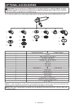
Page 11: ...5 model 1 Grip 36 2 Wheel Guard for grinding wheel 3 Inner flange Super flange 4 Depressed center wheel Flap disc 5 Lock nut 6 Back up pad 7 Flex wheel 8 Rubber pad 100 Rubber pad 115 9 Abrasive disc 10 Sanding lock nut 11 Wire wheel brush 12 Wire cup brush 13 Wheel Guard for cut off wheel 1 14 Abrasive cut off wheel Diamond wheel Lock nut wrench NOTE 1 In some European countries when using a diam...

Page 12: ...www makita com Makita Jan Baptist Vinkstraat 2 3070 Belgium Makita Corporation Anjo Aichi Japan 885463 225 EN 20150812 ...

Reviews: