

4
ENGLISH
(Original instructions)
Explanation of general view
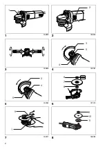
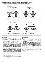
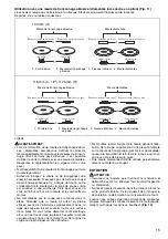
1
Shaft lock
2
Switch lever
3
Wheel guard
4
Screw
5
Bearing box
6
Lock nut
7
Depressed center grinding
wheel/Multi-disc
8
Inner flange
9
Lock nut wrench
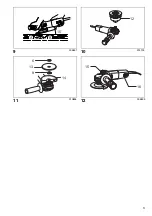
10
Abrasive disc
11
Rubber pad
12
Wire cup brush/Wire bevel
brush
13
Abrasive cut-off wheel/diamond
wheel
14 Wheel guard for abrasive cut-off
wheel/diamond wheel
15 Exhaust vent
16 Inhalation vent
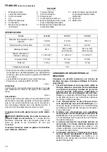
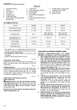
SPECIFICATIONS
• Due to our continuing program of research and devel-
opment, the specifications herein are subject to change
without notice.
• Specifications may differ from country to country.
• Weight according to EPTA-Procedure 01/2003
ENE048-1
Intended use
The tool is intended for grinding, sanding and cutting of
metal and stone materials without the use of water.
ENF002-2
Power supply
The tool should be connected only to a power supply of
the same voltage as indicated on the nameplate, and can
only be operated on single-phase AC supply. They are
double-insulated and can, therefore, also be used from
sockets without earth wire.
GEA010-1
General Power Tool Safety Warnings
WARNING Read all safety warnings and all
instructions.
Failure to follow the warnings and
instructions may result in electric shock, fire and/or
serious injury.
Save all warnings and instructions for future refer-
ence.
GEB033-7
GRINDER SAFETY WARNINGS
Safety Warnings Common for Grinding, Sanding,
Wire Brushing, or Abrasive Cutting-Off Operations:
1.
This power tool is intended to function as a
grinder, sander, wire brush or cut-off tool. Read
all safety warnings, instructions, illustrations
and specifications provided with this power tool.
Failure to follow all instructions listed below may
result in electric shock, fire and/or serious injury.
2.
Operations such as polishing are not recom-
mended to be performed with this power tool.
Operations for which the power tool was not designed
may create a hazard and cause personal injury.
3.
Do not use accessories which are not specifi-
cally designed and recommended by the tool
manufacturer.
Just because the accessory can be
attached to your power tool, it does not assure safe
operation.
4.
The rated speed of the accessory must be at
least equal to the maximum speed marked on
the power tool.
Accessories running faster than
their rated speed can break and fly apart.
5.
The outside diameter and the thickness of your
accessory must be within the capacity rating of
your power tool.
Incorrectly sized accessories can-
not be adequately guarded or controlled.
6.
Threaded mounting of accessories must match
the grinder spindle thread. For accessories
mounted by flanges, the arbour hole of the
accessory must fit the locating diameter of the
flange.
Accessories that do not match the mounting
hardware of the power tool will run out of balance,
vibrate excessively and may cause loss of control.
Model
9556HN
9557HN
9558HN
Depressed center wheel diameter
100 mm
115 mm
125 mm
Max. wheel thickness
6.4 mm
6.4 mm
6.4 mm
Spindle thread
M10
M14 or 5/8”
(country specific)
M14 or 5/8”
(country specific)
Rated speed (n) / No load speed (n
0
)
11,000 min
–1
11,000 min
–1
11,000 min
–1
Overall length
271 mm
271 mm
271 mm
Net weight
1.9 kg
2.0 kg
2.1 kg
Safety class
/II