8
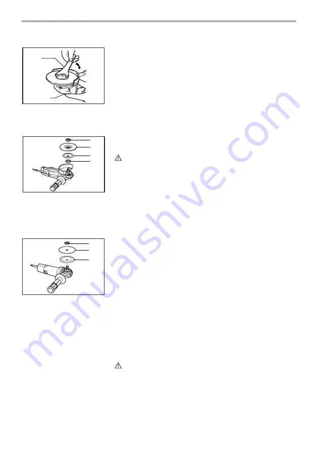
To tighten the lock nut, press the shaft lock firmly so that the
spindle cannot revolve, then use the lock nut wrench and
securely tighten clockwise.
To remove the wheel, follow the installation procedure in
reverse.
Installing or removing flex wheel
(optional accessory)
WARNING:
•
Always use supplied guard when flex wheel is on tool.
Wheel can shatter during use and guard helps to reduce
chances of personal injury.
Follow instructions for depressed center grinding wheel/
Multi-disc but also use plastic pad over wheel. See order of
assembly on accessories page in this manual.
Installing or removing abrasive disc
(optional accessory)
NOTE:
•
Use sander accessories specified in this manual. These
must be purchased separately.
Mount the rubber pad onto the spindle. Fit the disc on the
rubber pad and screw the lock nut onto the spindle. To
tighten the lock nut, press the shaft lock firmly so that the
spindle cannot revolve, then use the lock nut wrench and
securely tighten clockwise.
To remove the disc, follow the installation procedure in
reverse.
OPERATION
WARNING:
•
It should never be necessary to force the tool. The
weight of the tool applies adequate pressure. Forcing
and excessive pressure could cause dangerous wheel
breakage.
•
ALWAYS replace wheel if tool is dropped while grinding.
1. Lock nut wrench
2. Shaft lock
1
2
001083
1. Lock nut
2. Flex wheel
3. Plastic pad
4. Inner flange
1
4
3
2
001095
1. Lock nut
2. Abrasive disc
3. Rubber pad
1
3
2
001106


