background image

Terminals

R

epair

P 3 / 5 

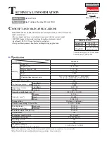
[2] Removal/Installation of Motor from/on Gear Assembly (cont.)

[3] Installing Speed change Lever

Fig. 6

Fig. 7

Fig. 5

Fig. 9

Fig. 10

Fig. 8

INSTALLATION

1) Place Motor bracket as illustrated in Fig. 5,
    and fasten it to Motor with two Pan head
    screws.
2) Aligning the protrusions on Motor bracket
    with the grooves in Gear assembly,
    assemble Motor to Gear assembly. (Fig. 6)
3) Assemble Motor to Gear assembly while
    turning it in the clockwise direction when
    viewed from the terminal end of Motor.
    (Fig. 7)

1) Make sure that two Compression springs are set in place on Speed change lever
    as illustrated in Fig. 8.
2) Install Speed change lever onto the protrusion on Gear assembly as illustrated
    in Fig. 9.
    After installation, slide Speed change lever to either side. (Fig. 10

Protrusions on
Motor bracket

Grooves in Gear assembly

Motor

Motor

Motor bracket

Gear assembly

Gear assembly

Pan head screw

Protruding side

Motor

Motor bracket

Side without protrusion

Red marking

Speed change lever side

Trigger switch side

Place Motor bracket
so that its protruding
side is positioned on
the opposite side to the
red marking on Motor.

Compression
springs

Gear assembly

Motor

Compression springs

Protrusion

Speed change
lever

Speed change lever

Protrusion

Speed change lever

Summary of Contents for 8280D

Page 1: ...hout Note The standard equipment listed above may differ from country to country Bit 2 65 Model No Battery cover Plastic carrying case 8280DZ 1 No No 1 Yes 2 Battery 1420 Battery PA14 Battery 1422 Battery 1434 Battery 1435 Battery 1435F Charger DC1414 Charger DC1804 Charger DC1439 Automotive charger DC1422 Automotive charger DC1822 Assorted drill bits for wood Assorted drill bits for steel Assorte...

Page 2: ...rward rotation mode INSTALLATION 1 Secure one end of a hex wrench with Chuck jaws and the other with vise Shift Speed change lever to Low and set the machine in the mode of drilling in forward rotation Hold the grip of the machine firmly so that your hand cannot be pulled away by reaction torque And then fasten Spindle to Drill chuck by pulling the trigger of Switch until Spindle is locked Fig 2 N...

Page 3: ...mpression springs are set in place on Speed change lever as illustrated in Fig 8 2 Install Speed change lever onto the protrusion on Gear assembly as illustrated in Fig 9 After installation slide Speed change lever to either side Fig 10 Protrusions on Motor bracket Grooves in Gear assembly Motor Motor Motor bracket Gear assembly Gear assembly Pan head screw Protruding side Motor Motor bracket Side...

Page 4: ...r to set Leaf spring in place on housing L as illustrated in Fig 11 5 Installing F R Change Lever Install F R change lever onto Trigger switch by placing the boss on Trigger switch between the prongs on F R change lever as illustrated in Fig 12 Housing L Leaf spring boss boss prongs F R Change lever Trigger switch prongs ...

Page 5: ...ousing Route lead wires as illustrated in Fig 14 3 Connecting Lead Wires with Battery Holder Connect lead wires with the terminals on Battery holder as illustrated in Fig 15 D C Motor Switch Battery holder Hold the lead wires with lead wire holder Do not put lead wires on this rib Lead wire red Lead wire black Fig 13 Fig 14 Fig 15 Do not put lead wire black on this rib Lead wire red Lead wire blac...

Reviews: