Models No.
Description
PRODUCT
T
ECHNICAL INFORMATION
C
ONCEPTION AND MAIN APPLICATIONS
S
pecification
S
tandard equipment
O
ptional accessories
< Note > The standard equipment for the tool shown may differ from country to country.
P 1 / 6
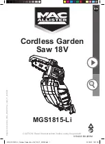
Cordless Jig Saw
4331D, 4333D
The above models have been developed as a series of the
top-handle type of cordless jig saw.
* Model 4331D : 12V type with variable speed control feature
* Model 4333D : 14.4V type with variable speed control feature
W
L.2
H
L.1
Dimensions : mm ( " )
Width ( W )
Height ( H )
Length ( L.1 )
70 (2-3/4)
217 (8-1/2)
280 (11)
153 (6)
Length ( L.2 )
The variations of these models are as follows.
4331DWD
4331DWAE
4331DWDE
4333DWD
4333DWAE
4333DWDE
Model No.
Battery
Charger
*Charging time for
one battery pack
Ni-MH 1234 : 1 pc.
Ni-Cd 1222 : 2 pcs.
Ni-MH 1234 : 2 pcs.
Ni-MH 1434 : 1 pc.
Ni-Cd 1422 : 2 pcs.
Ni-MH 1434 : 2 pcs.
DC1411
DC1411
DC1411
DC1411
DC1411
DC1411
approx.75 min.
approx.75 min.
approx.75 min.
approx.75 min.
approx.60 min.
approx.60 min.
*Charging time for one battery pack: The above time may change, which depends on the conditions
of battery, charger, etc.
Strokes per min.: (min
-1
= spm)
Model No.
Max.cutting
capacities
in wood: mm (")
in mild steel: mm (")
in aluminum: mm (")
Length of stroke : mm ( " )
4331D
4333D
500 - 2,800
500 - 2,600
26 (1)
65 (2-9/16)
10 (3/8)
20 (13/16)
*Jig saw blade set ....................1 set (including Jig saw blade No.B-10 : 2 pcs., BR-13 : 2 pcs., and B-22 : 2 pcs.)
*Hex wrench 3 ....................... 1 pc.
*Kerf board ....................... 1 pc.
*Plastic carrying case ............. 1 pc.
* Jig saw blades of MAKITA type : No. 1 - 5, No.8 - 10, No.16, No.17, No.41, No.42, No.BR-3
* Jig saw blades of B type : No.51, No.58, 59, B-10 - B19, B-21 - B-27, B16L, BR-13
* Battery 1200, 1202, 1201A, 1220, 1222, 1234, 1235 (for 4331D)
* Battery 1420, 1422, 1433, 1434, 1435 (for 4332D and 4333D)
* Rip fence
* Circular guide
* Protector
* Plastic base plate
* Kerf board set
* Hose set
* Vacuum head
* Battery cover
* Charger DC1411
* Fast charger DC1422
* Fast charger DC1439