background image

Summary of Contents for 3612B

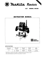
Page 1: ...1 2 MODEL 3612B Collet chuck Main body No load Overall capacity stroke speed length INSTRUCTION MANUAL Net weight DOUBLE INSULATION 112 0 65 mm 23 000 287 mm 5 7 kg 0 2 9 16 R min 11 5 16 12 7 Ibs ...

Page 2: ...OOL Don t force small tool or attachment to do the job of a heavy duty tool Don t use tool for purpose not intended DRESS PROPERLY Don t wear loose clothing or jewelry They can be caught in moving parts Rubber gloves and non skid footwear are recommended when working outdoors Wear protective hair covering to contain long hair USE SAFETY GLASSES Also use face or dust mask if cutting operation is du...

Page 3: ...inding of moving parts breakage of parts mounting and any other conditions that may affect its operation A guard or other part that is damaged should be properly repaired or replaced by an authorized serv ice center unless otherwise indicated elsewhere in this instruction manual Have defective switches replaced by authorized service center Don t use tool if switch does not turn it on and off GUARD...

Page 4: ... Before using the tool on an actual workpiece let it simply run for several minutes first Watch for flutter that might be caused by poor installation or a poorly balanced cracked or damaged bit immediately fore operation 9 Be careful of the bit rotating direction and the feed direction IO Do not leave tool running Operate the tool only when hand held 11 Always switch off and wait for the bit to co...

Page 5: ...e Either can lead to collet chuck breakage Adjusting cutting depth Release the lock lever and lower the tool to the desired depth Then pull up on the lock lever to lock Now adjust the stopper block and pole so that even if the lock lever is released the router stops at the uniform depth If you press the fast feed button on the stopper pole the pole can be advanced rapidly Ordinarily the pole moves...

Page 6: ...re than required in relation to the base plate surface turn the nylon nut to lower the upper limit for more effective routing CAUTION 0 Do not lower the nylon nut too low or the bit will dangerously protrude 0 Before operating the tool check to be sure that the router automatically rises to the upper limit Switch action To start the tool position the switch lever to ON side To stop to OFF side CAU...

Page 7: ...ce while routing CAUTION 0 When doing edge routing the workpiece surface should be on the left side of the bit in the router feed direction or a dangerous kickback may result 3 Bit revolving direction Correct bit feed direction 0 Adjustment should not be more than 15 mm 5 8 a t once when using straight bit 7 ...

Page 8: ...olts A To obtain the desired dis tance between the bit and the straight guide turn the fine adjustment screw 1 5 or 1 16 per turn Then tighten the thumb bolt B to secure the straight guide in place By bolting larger pieces of wood onto the straight guide an even larger wider guide can be obtained as shown When using a board jointing bit attach pieces of wood to the straight guide which have a thic...

Page 9: ... bit and the guide surface can be adjusted by the fine adjustment screw 1 5 mm or 1 16 per turn When the thumb bolt C is released the guide roller can be moved 1 1 f Guide roller 1 ment screw I Thumb bolt B I Thumb bolt C I Templet guide The templet guide provides a sleeve through which the router bit passes when making exact duplicates of a given pattern templet The templet guide is installed by ...

Page 10: ...about 6 mm 1 4 or less Keep the brushes clean and free to slip in the holders Both brushes should be changed a t the same time Use only Makita carbon brushes 0 Use a screwdriver to remove the brush holder cap as shown on the figure Take out the worn brush insert the new one and secure the brush holder cap k 4 6mm 1 4 BNSh holder cap Any other maintenance should be performed by an Authorized Makita...

Page 11: ...ed manner Templet guide Used for finishing a large quantity of articles of complicated shapes with the use of a templet mml Part NO I Templet w d e I A I E I C Pari No 321492 3 Templet guide adapter A E C 30 11 3 15 I 35 11 3 8 1 1 7 19132 l Collet sleeve Use a sleeve which fits for the diameter of the bit shank s 2e Part No Pirt No s Le Straight guide Part No 342428 9 Wrench 24 Part No 781210 5 T...

Page 12: ... 1 1 1 8 114 2 3 16 HIGH SPEED STEEL STRAIGHT 2 Flute PART NO A B C 0 E 733233 4A 5 16 7 8 1 3 16 1 4 2 118 733234 2A 1 2 718 1 1 8 1 4 2 118 STRAIGHT 2 Flute 1 2 Shank CARBIDE TIPPED PART NO 7330054A 1 1 4 2 1 2 733005 6A 1 1 4 1 7 16 2 718 733005 8A 112 1 1 2 1 1 4 733006 4A 3 4 1 1 4 1 1 4 112 2 112 733006 6A 7 8 1 1 4 1 3 16 1 2 2 112 733006 8A 1 1 4 1 3 16 112 2 1 2 HINGE MORTISING CARBIDE TI...

Page 13: ... 114 1 718 733008 4A 318 9116 1 114 114 2 7330086A 112 11116 1 114 114 2 3116 733008 8A 518 11116 1 114 114 2 114 733009 0A 314 13116 1 114 114 2 318 CORE BOX 4D c J HIGH SPEED STEEL PART NO A B C D E 733238 2A 114 114 1 3116 114 1 112 I I VEE GROOVING CARBIDE TIPPED PART NO A B C D E F 733009 2A 114 112 1 3 16 114 2 318 733009 4A 7116 314 15 16 114 2 518 13 ...

Page 14: ...2 112 3 114 HIGH SPEED STEEL PART NO A B C D E 733236 0A 114 314 1 114 2 7116 CORNER ROUNDING CARBIDE TIPPED Ball Bearing Pilot PART NO A B C 0 E 733120 OA 3 16 318 1 1 4 114 1 15 16 733120 2A 1 4 1 2 1 1I4 114 2 733120 4A 5 16 112 1 114 114 2 1 16 733120 6A 318 518 1 1 4 1I4 2 118 733120 8A 1 2 314 1 114 114 2 114 733121 0A 318 5 8 1 112 112 2 318 733121 2A 112 314 1 1I2 1 2 2 112 REPLACEMENT BEA...

Page 15: ...1 114 1 518 733122 8A 318 112 1 114 1 314 733123 0A 112 518 1 114 1 718 i REPLACEMENT BEARING NO 733132 2A HIGH SPEED STEEL Solid Pilot PART NO A B C D E 733242 6A 114 112 1 114 1 314 733242 BA 318 314 1 114 2 1 32 45 CHAMFERING 4 D I CARBIDE TIPPED Ball Bearing Pilot PART NO A 3 C D E F 733124 4A 112 112 1 114 114 2 114 1 3116 REPLACEMENT BEARING NO 733132 4A RABBETING 1DC CARBIDE TIPPED Ball Bea...

Page 16: ...LID CARBIDE PART NO A B C D E 733128 0A 1 4 1 4 1 1 16 114 1 9 16 7 BEVEL TRIMMER Self Piloting SOLID CARBIDE PART NO A B C D E 733128 2A 3 16 1I 4 1 1 16 114 1 9 16 2 FLUTE FLUSH TRIMMER CARBIDE TIPPED I PARTNO A B C D E 733128 8A 3 8 1 1 1I 4 114 2 1 16 733128 9A 1I2 1I2 1 114 114 2 1 16 733129 OA 112 1 1 1 4 114 2 518 3 8 REPLACEMENT BEARING NO 733132 2A 112 REPLACEMENT BEARING NO 7331324A 16 ...

Page 17: ...RT NO A 8 C D E 733129 2A 518 318 1 114 114 2 318 REPLACEMENT BEARING NO 733132 6A 3 FLUTE 22 BEVEL TRIMMER ASSEMBLY Self Piloting SOLID C RBlDE CUTTER PART NO A B C 0 E 733129 4A 518 3 8 1 114 114 2 318 REPLACEMENT BEARING NO 733132 6A 3 FLUTE FLUSH REPLACEMENT CUTTER T L A p J SOLID CARBIDE PART NO A B C 733129 6A 3 8 114 518 FOR FLUSH TRIMMER ASSEMBLY NO 733129 2A 17 ...

Page 18: ...33129 8A 318 FOR BEVEL TRIMMER 1 4 REPLACEMENT ARBOR PART NO A B C D E 733131 2A 1 4 318 1 114 1I 4 2 318 FOR FLUSH TRIMMER ASSEMBLY NO 733129 2A AND NO 733129 4A BALL BEARING PILOT PART NO A B 733132 2A 318 O D 118 I D 733132 4A 1 2 OD 3 16 I D 733132 6A 5 8 O D 1 4 ID 18 ...

Page 19: ...Jan 24 E6 EN 12 mm 1 2 ROUTER Model 3612B 19 ...

Page 20: ... other part Specifications may differ from country to country f MAKITA LIMITEDONE YEARWARRANTY Warranty Policy Every Makita tool is thoroughly inspected and tested before leaving the factory It is warranted to be free of defects from workmanship and materials for the period of ONE YEAR from the date of original purchase Should any trouble develop during this one year period return the COMPLETE too...

Reviews: