background image


UDD-SD-116/


Release Date: 31.12.2014/Rev No: 1/Rev. 

Date

: 27.04.2015


24


Press and hold 

 for more than 2 seconds: Circularly and orderly display the items every 2 

seconds, when press and hold the key for some time again, it will turn to output status. 
Function setting mode: 
Press and hold the key 

or

 for more than half a second (less than 2 seconds): Select the 

set option. 

 FUNCTION SETTING KEY 


Non-function setting mode: 
Press and hold the key for more than 2 seconds: Function setting interface. 
Function setting mode: 
Press and hold the key for more than half a second (less than 2 seconds): Enter the function 
setting option. 
Press and hold the key for more than 2 seconds: exit from this function setting interface. 

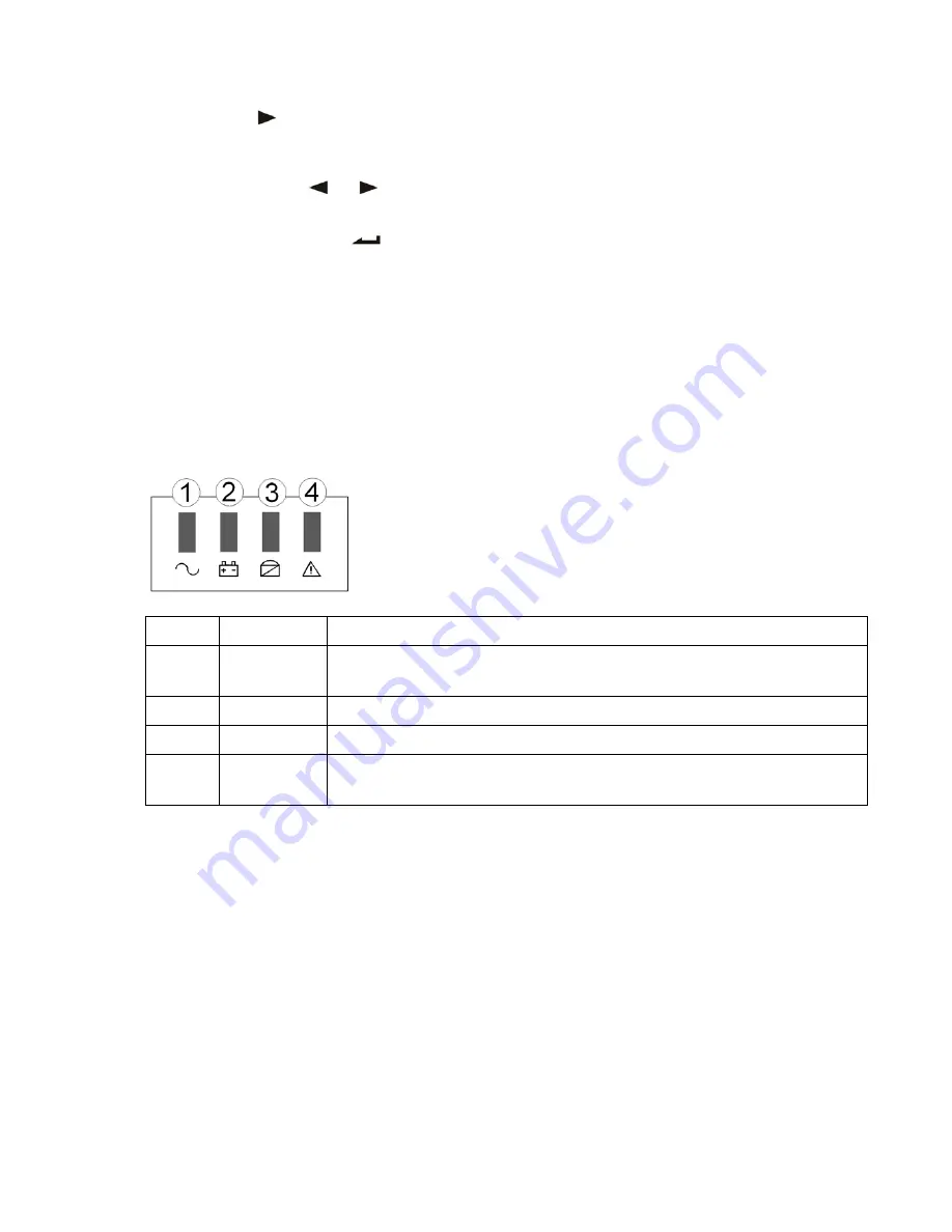
4.2 LED Function 


Number 

LED 

Explanation 

① 

Inverter LED  Inverter green LED is on: UPS is normally powered by Line mode or ECO 

mode or BAT mode. 

② 

Battery LED  Battery yellow LED is on: Battery mode. 

③ 

Bypass LED  Bypass yellow LED is on: Bypass mode or ECO mode, etc. 

④ 

Warning LED  Warning red LED is on: UPS fault. For example: Overload beyond the 

allowed time, inverter fault, BUS fault, over temperature fault, etc 


PS: LED display detail in different mode is listed at the back. 

4.3 LCD Display Function 

LCD displays as following figure. 


Summary of Contents for PowerPack SE 1 kVA

Page 1: ...USER MANUAL POWERPACK SE SERIES 1 10 KVA...

Page 2: ...1 UDD SD 116 Release Date 31 12 2014 Rev No 1 Rev Date 27 04 2015...

Page 3: ...2 UDD SD 116 Release Date 31 12 2014 Rev No 1 Rev Date 27 04 2015 USER MANUAL POWERPACK SE SERIES 1 10 KVA UDD SD 116...

Page 4: ...to all the warning and operation information It is not advisable to install or operate the machine before reading this manual Shipment Carrying vehicles or handling accessories must have enough featur...

Page 5: ...r Installation and Output Connection 11 3 4 Parallel System of 6 20K UPS Installation 14 3 4 1 Parallel System Installation 15 3 5 External Battery Connection Procedure for Long Back up Type 19 3 6 Ne...

Page 6: ...etting 31 4 7 Parameters Inquiring Operation 32 5 WORKING MODE INTRODUCTION 34 5 1 Bypass Mode 34 5 2 Line Mode 35 5 3 Battery Mode 35 5 4 ECO Mode 35 5 4 Fault Mode 36 6 THE WARNING CODE LIST OF THE...

Page 7: ...le will be shortened as environment temperature rise Replacing battery periodically can help to keep UPS in normal state and assure backup time required Battery replacement should be done by authorize...

Page 8: ...turn to the carrier and dealer To determine whether this UPS is the model you want to buy Check the model name showed both on the front panel and rear panel of UPS to confirm Model Type Model Type 1KV...

Page 9: ...TTERY RESET FUSE 250VAC INPUT 2 1 6 8 10 7 4 5 9 TEL MODEM FAX OUT IN USB EPO OUTPUT SOCKET RS232 96VDC 30A EXT BATTERY RESET FUSE 250VAC INPUT 2 1 6 8 10 7 4 5 9 3 a 0 9PF 1KVA rear panel b 0 9PF 1 5...

Page 10: ...F 1KVA rear panel b 0 9PF 2KVA rear panel c 0 9PF 3KVA rear panel 1 Input Power Terminal 2 Over Current Protector 3 Fan 4 USB 5 Emergency Power Off 6 RS232 Communication Interface 7 Intelligent Slot 8...

Page 11: ...ximum input current of the UPS 8 All the power socket should be configured with earthing device for safety 9 UPS could be electrified or powered no matter the input power cable is tied or not even whe...

Page 12: ...Output Ground N L L N Battery Protector Over Current RESET R E S E T T O Input Output 3 3 6 10K UPS With Isolation Transformer Installation and Output Connection For the type of 6 10KVA which contains...

Page 13: ...Caution only for long run type UPS 1 Make sure a DC breaker or other protection device between UPS and external battery pack is installed if not Please install it carefully Switch off the battery bre...

Page 14: ...e 50 of UPS rating power Connect one load to L1 N1 and the other load to L2 N2 Option 2 GND L1 N1 L2 N2 To Load L2 L1 After connecting L1 L2 and N1 N2 it becomes one low voltage output 100V 110V 115V...

Page 15: ...d high voltage at the same time like option 4 it will cause the L1 N1 L2 N2 with low voltage loads in Non Isolated status we recommend that you may only use two low voltage at L1 N1 or L2 N2 like opti...

Page 16: ...spec table above in attention items Each UPS input wiring please comply with the requirements of single UPS wiring Every UPS is recommended to connect together to one common utility power terminal blo...

Page 17: ...ow many parallel wires you need Parallel system of two UPS wiring Parallel system of three UPS wiring Caution For three UPS parallel system or more than three unites system type please remove the shor...

Page 18: ...terminal block Connect input cables of all UPS together to one common utility power terminal block I n p u t c o m m o n t e r m i n a l b l o c k U t i l i t y p o w e r s u p p l y O u t p u t c o m...

Page 19: ...n p u t B A T 1 B A T 2 N BAT L N L BAT O u t p u t B A T 3 Wiring diagram for thee UPS parallel system If the UPS is the standard type each UPS has batteries inside already If the UPS is the long ru...

Page 20: ...second less than 4 seconds it would turn off single UPS you choose of course if you need to turn on it again or turn on any other single UPS of the system just press ON KEY of that UPS to start it Pa...

Page 21: ...ng work automatically For the type of 1 3K UPS please connect the battery pack to the battery slot For the type of 6 10k UPS please connect the battery pack to the terminal block Make sure all cables...

Page 22: ...useful simple way is pulling it out 3 6 3 Intelligent Card Option This series High frequency online UPS supply a intelligent slot on rear panel it s for SNMP card dry contact and USB card users could...

Page 23: ...on please No 1 Rev D input powe elligent slot Foot PIN1 PIN2 PIN3 PIN4 PIN5 PIN6 PIN7 PIN8 PIN9 equency onl contact to Date 27 04 er and even t it s anoth Defin 1 ON 2 ON 3 Groun 4 Remo 5 Comm 6 ON 7...

Page 24: ...keys for more than half a second to turn on the UPS OFF KEY Press and hold the two keys for more than half a second to turn off the UPS TEST MUTE KEY Press and hold the two keys for more than 1 secon...

Page 25: ...ess and hold the key for more than half a second less than 2 seconds Enter the function setting option Press and hold the key for more than 2 seconds exit from this function setting interface 4 2 LED...

Page 26: ...ke input b Fault code w could adjust umber and s power capa s area will BYPASS Byp Mode E Constant Fr No 1 Rev D ry capacity ight will blin ry disconnec ation when aulty the ico ery mode b t mode oth...

Page 27: ...ey for more than half a second to start UPS 2 The operation of UPS in the process of start is almost the same as that when mains power is on After the self test finishes the corresponding LED lights a...

Page 28: ...ECO will flash 2 Enter the ECO setting interface Press and hold the function setting key for more than half a second less than 2 seconds then come to setting interface of ECO at this time the letters...

Page 29: ...ted and the ON or OFF will light without flash 4 Press and hold the function setting key for more than 2 seconds exit from the setting interface and return to main interface 5 After setting BPS ON wit...

Page 30: ...more than half a second less than 2 seconds select the function setting choose battery voltage setting interface at the moment the letters bat will flash 2 Enter the battery voltage selecting interfac...

Page 31: ...hold the function setting key for more than half a second less than 2 seconds then come to setting interface of CF at this time the letters CF will not flash any more The ON or OFF will flash Press a...

Page 32: ...ined by yourself the default value is 50HZ 4 Confirm the OPF selecting interface After selecting 50HZ or 60HZ press and hold the function setting key for more than half a second less than 2 seconds No...

Page 33: ...age setting in or more than nd the nume erface Press exit from th ore doing pa Operation ey or red items in reen are sho oltage and o 20V the outp No 1 Rev D s are 1 2 3 nterface Aft n half a seco er...

Page 34: ...e of the a wing graphic ormal phen maximum te maximum te frequency o cy is 50Hz nd capacity o ltage is 192V ned accordi No 1 Rev D ctive power cs shows th omenon to s emperature emperature of the inpu...

Page 35: ...ain within 30s it will return to output status 5 WORKING MODE INTRODUCTION 5 1 Bypass Mode LED indications on front panel in bypass mode are as following Bypass yellow LED is on the buzzer beeps once...

Page 36: ...s once every 4 seconds The warning red LED will be on while beeping When the mains power is low or unstable UPS will turn to battery mode at once 5 4 ECO Mode LED indications on front panel in ECO mod...

Page 37: ...4 8 19 3 24 12 2014 Rev in Fault mo con which the fau rning LED is D display fau ng temporar when confir G CODE ANEL he fault co Fault Bus Bus Bus un Bus soft Inverter so No 1 Rev D de are as fo ult c...

Page 38: ...65 66 67 68 69 BUS shorted Yes 75 76 77 78 79 Communication fault Yes 80 81 82 83 84 Relay fault Yes 85 86 87 88 89 AC input SCR fault Yes unused 90 91 92 93 94 CAN fault Yes 95 96 97 98 99 ID conflic...

Page 39: ...for mains power overload 2 beeps sec Protect operation for mains power mode overload Long beep Warning for battery overload 2 beeps sec Protect operation for battery mode overload Long beep 6 Warning...

Page 40: ...UDD SD 7 TR When th 116 Releas ROUBL he system ru se Date 31 1 LE SHO uns in failur 12 2014 Rev OOTING e mode the Fault c No 1 Rev D G LCD will sh code Date 27 04 how as below 2015 w Fault icon 39...

Page 41: ...er Persistently alarm the fault code is 45 49 Output short circuited Turn of the UPS and disconnect all the load make sure there no any fault or internal short circuit of the load And then restart the...

Page 42: ...acity descend Please change new battery contact your supplier to get the new battery and spare parts UPS doesn t have any power go through even main power on UPS input breaker disconnects Please reset...

Page 43: ...tery Appendix 3 Specification Sheet 1 3KVA Rated Capacity 1KVA 1 5KVA 2KVA 3KVA Input Rated input voltage 220V or 120V Rated input frequency 50Hz 60Hz auto adaptive Input voltage range the type of 220...

Page 44: ...50 60 0 2 Hz Phase locked rate 1Hz s Total voltage harmonic distortion Full linear load 3 Full nonlinear load 5 Battery Battery type Sealed lead acid maintenance free battery Quantity 2 3 4 4 6 6 8 DC...

Page 45: ...er time From BAT mode to AC mode 0ms transfer time Efficiency Line mode 92 BAT mode 91 ECO mode 98 Output frequency Line mode Same as input frequency BAT mode 50 60 0 2 Hz CUCF mode 50 60 0 2Hz Phase...

Page 46: ...215 144 410 215 190 452 341 190 452 341 190 470 341 190 452 341 190 470 341 Weight Kg Long 6 6 10 12 12 12 5 12 5 Standard 10 13 5 18 20 25 24 29 Rated Capacity 6KVA 6KVA Isolated 10KVA 10KVA Isolated...

Page 47: ...another product having similar features for the use of consumers until the faulty product has been repaired Even though consumers exercise their repair rights they can claim free replacement of produ...

Page 48: ...that legible barcode serial number belonging to the product be on the product Otherwise it is not covered in the scope of the guarantee It is essential that products to be sent through freight defini...

Page 49: ...rs Damages and breakdowns resulting from treatments internally or externally tampering efforts to repair and spare part replacement of products without approval of MAKELSAN and those resulting from tr...

Page 50: ...UDD SD 116 Release Date 31 12 2014 Rev No 1 Rev Date 27 04 2015 49...

Page 51: ...anayi B lgesi 2 Yol I 5 Parsel 34956 Tuzla stanbul Tel 0216 428 65 80 Fax 0216 327 51 64 E mail makelsan makelsan com tr zmir Office Halkap nar Mah 1348 Sok 2AE Keremo lu Merkezi Yeni ehir zmir Tel 02...

Page 52: ...Tuzla stanbul Tel 0216 428 65 80 Fax 0216 327 51 64 E mail makelsan makelsan com tr zmir Office Halkap nar Mah 1348 Sok 2AE Keremo lu Merkezi Yeni ehir zmir Tel 0232 469 47 00 Fax 0232 449 47 00 E ma...

Reviews: