


9
USER
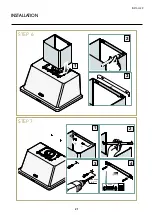
INSTRUCTIONS FOR USE
Light controls
Infrared lamp control
Press the key once to turn on the left lamp
Press the key twice to turn on the right lamp
Press the key 3 times to turn off the lamps
ON-OFF
key, turns the hood on and off by setting it to speed 1
speed 1:
keeps the air clean with low electricity consumption;
24-hour air recycling:
is turned on with the motor off by pressing “0/1” for 5 seconds,
the motor turns on at the first speed for 5 minutes every 20 minutes, the altered
operation has a total duration of 24H.
To turn it on, press and hold key 1 for 7 seconds.
Speed 2:
normal conditions of use.
Speed 3:
extraction of particularly intense fumes and odours
(e.g. frying or cooking on a hot plate)
Intense speed:
starts the motor at maximum speed for 5 minutes, then automatically
returns to speed 3.
Auto switch-off:
to activate the auto switch-off, the hood must be switched on and
then the “light control” key must be pressed for 5 seconds until all the LEDs begin to
flash, by subsequently pressing one of the keys (0/1, 2, 3 ) the auto switch-off time
can be programmed which will differ according to the key pressed:
0/1 = 5’, 2 = 10’, 3 = 15’, = 20’. During the auto shut-off time, it is possible to
change the set speed. During the auto shut-off, the LED corresponding to the chosen
time flashes
0/1
2
3
0/1
2
3
0/1
2
3
0/1
2
3
0/1
2
3
0/1
2
3
0/1
2
3
Fig. 2.
CONTROL PANEL
Summary of Contents for UAM76
Page 2: ......
Page 19: ...19 INSTALLER INSTALLATION STEP 2 STEP 3 2 1 OK ...
Page 20: ...20 INSTALLATION STEP 4 STEP 5 1 2 3 2 1 NON FORNITA NOT PROVIDED ø8 mm ø 05 16 NOT PROVIDED ...
Page 21: ...21 INSTALLER INSTALLATION STEP 6 STEP 7 1 3 4 2 2 3 1 ø8 mm ø 05 16 40 mm 137 64 ...
Page 22: ...22 INSTALLATION STEP 8 STEP 9 ...
Page 23: ...23 INSTALLER INSTALLATION STEP 10 STEP 11 2 1 150 mm 5 29 32 min 3 2 1 3 4 ...
Page 24: ...24 INSTALLATION STEP 12 STEP 13 2 3 4 1 ø8 mm ø 05 16 40 mm 137 64 ...
Page 25: ...25 INSTALLER INSTALLATION STEP 14 STEP 15 1 2 ...