


8
Fig. 1.
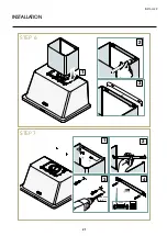
INSTRUCTIONS FOR USE
Product’s operation
The hood extract fumes and steam generated during
cooking from the environment, channelling them through
metal filters that must be regularly removed and washed.
And then, depending on the type of installation, fumes
and steam:
are
driven outside
from the building through a
drain pipe: ducting or external drain cooker
hood - Fig. 1.
Operating instructions
The hood must be switched on
at least a couple of minu-
tes
before starting to cook, to promote the suction of fumes
and steam.
After finishing cooking, leave the hood in operation for an
extra few minutes: in this case, it may be appropriate to
activate the
“Timer”
function, which automatically switches
the hood off after
10 minutes
of operation at speed 2.
The page that follows shows how to use the control
panel.
What speed should I use?
The unit operates at three different speeds:
speed 1
: purifies the air whilst limiting electricity consump-
tion;
speed 2
: normal conditions of use (e.g. steam suction)
speed 3
: for the elimination of particularly intense fumes
and smells (e.g: when frying or grilling).
When should the filters be washed or replaced?
The hood has two types of filters:
metal filters
: these must be removed and
washed
at least
once a month. For the cleaning procedure refer to chapter
“
Cleaning
“ on page 11.
cappa ad
evacuazione
esterna
vapori
fumi e
fumi e
vapori
cappa
a ricircolo
interno
metallici
metallici
carbone
attivo
external
evacuation
hood
fumes and
steam
metal filters
Summary of Contents for UAM76
Page 2: ......
Page 19: ...19 INSTALLER INSTALLATION STEP 2 STEP 3 2 1 OK ...
Page 20: ...20 INSTALLATION STEP 4 STEP 5 1 2 3 2 1 NON FORNITA NOT PROVIDED ø8 mm ø 05 16 NOT PROVIDED ...
Page 21: ...21 INSTALLER INSTALLATION STEP 6 STEP 7 1 3 4 2 2 3 1 ø8 mm ø 05 16 40 mm 137 64 ...
Page 22: ...22 INSTALLATION STEP 8 STEP 9 ...
Page 23: ...23 INSTALLER INSTALLATION STEP 10 STEP 11 2 1 150 mm 5 29 32 min 3 2 1 3 4 ...
Page 24: ...24 INSTALLATION STEP 12 STEP 13 2 3 4 1 ø8 mm ø 05 16 40 mm 137 64 ...
Page 25: ...25 INSTALLER INSTALLATION STEP 14 STEP 15 1 2 ...