


8
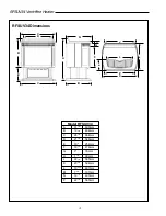
RFSUV34 Vent-Free Heater
FIRST FIRING
Upon completing your gas line connection, a small
amount of air will be in the lines. When first lighting
unit with pilot light, it will take a few minutes to purge
this air. Once the purging is complete, the pilot and
burner will light and operate as indicated in the
instruction manual. Subsequent lightings of the
heater will not require such purging.
IMPORTANT:
PLEASE REVIEW THE FOLLOWING
CAREFULLY
It is normal for fireplaces fabricated of steel
to give off some expansion and/or
contraction noises during the start up or cool
down cycle. Similar noises are found with
your furnace heat exchanger or car engine.
It is not unusual for your
Majestic gas
fireplace to give off some odor the
first time it is burned. This is due to
the curing of the paint and any
undetected oil from the manufacturing
p r o c e s s .
Please ensure that your room is well
ventilated - open all windows.
It is recommended that you burn your
Majestic fireplace for a least six (6) hours the
first time you use it. If optional fan kit has
been installed, place fan in the "OFF" position
during this time.
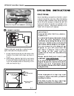
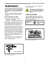
Flame impingement on logs may cause
excessive carbon monoxide production
resulting in sooting.
If the flame touches the logs, adjust logs
slightly so that there is no obstruction.
OPERATING INSTRUCTIONS
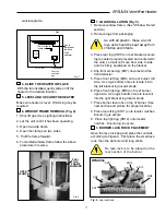
9. REMOTE SWITCH
Install on/off switch assembly on either the rear
right or left side of the fireplace cabinet.
1. Position switch assembly onto the back of the
fireplace, then fasten two screws as shown in
Fig. 8.
2. Attach wiring under the clips on the rear casing
(Fig. 8) and install wiring through the rear open-
ing of the fireplace before connecting to the
valve as shown in Fig. 7.
PILOT
ADJ
TH
TP
TP TH
Fig. 8
Screw
(through existing hole)
Screw
On/off switch
assembly
Clips
Wiring for milli-volt
gas valves
Fig. 6
Fig. 7
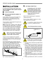
AREA TO PLACE THE BURNER LAVA ROCK


