


6
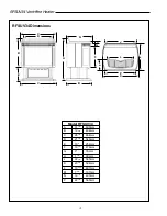
RFSUV34 Vent-Free Heater
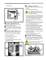
It will be easier to install the fan before
connecting the gas line to the fireplace.
1. Open front access door panel by pulling forward
on handle.
2. Fig. 3. Install the fan through the opening at
the back of the pedestal, with the outlet pointed
up and the fan mounting bracket facing the back
of the fireplace. The fan mounts over two studs
which hold the fan just below the firebox floor.
Hold the fan in place with the two nuts provided.
3. Locate the fan speed control/junction box on
screw studs provided on base of the fireplace.
Tighten with nuts.
4. Install thermal sensor element on screw studs
located to the right of the gas valve on the burner
base.
5. Plug in grounded service cord to a convenient
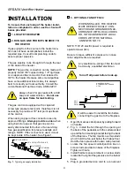
C
B
A
Black
White
Ground
A: SPEED CONTROL
B: TEMPERATURE SENSOR
C: FAN
3. OPTIONAL FAN KIT FK24
WHEN INSTALLED, THE HEATER
MUST BE ELECTRICALLY CON-
NECTED AND GROUNDED IN AC-
CORDANCE WITH LOCAL CODES
OR, IN THE ABSENCE OF LOCAL
CODES WITH THE NATIONAL
ANSI/NFPA NO. 70.
NOTE: 110/120 electric power is required to
operate blower (fan).
Be sure to leave sufficient excess wire in case
minor adjustments are required.
Any electrical re-wiring of this fan must
be done by a qualified electrician.
Turn off all power before hook-up.
INSTALLATION
To be sure that each step of the heater instal-
lation is completed in order, use the check-off
boxes provided.
1. LOCATE THE HEATER
2. RUN GAS LINE FROM ITS SOURCE TO
THE HEATER
If gas piping from the source to the heater loca-
tion has not been accomplished, install the
required pipe. Consult local plumbing code to
assure proper pipe size.
The gas pipeline to be brought in through the rear
or the base of the heater.
NOTE: The gas line connection can be made with
properly tinned 3/8" copper tubing, 1/2" rigid pipe
or an approved flex connector, then reduced to
3/8" to the heater. Because some municipalities
have some additional local codes, it is always
best to consult your local authority. Consult the
current National Fuel Gas Code, ANSI Z223.1
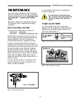
Always check for gas leaks with a mild
soap and water solution. Do not use
an open flame for leak testing.
The gas control is equipped with a captured
screw type pressure test point, therefore it is not
necessary to provide a 1/8" test point up stream
of the control.
When using copper or flex connector use only
approved fittings. Always provide a union when
using back iron pipe so that gas line can be
easily disconnected for burner or fan servicing.
See gas specification for pressure details and
ratings. NOTE: If flex connector is used, it must
be kept inside of the heater. See Figure 1.
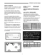
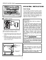
Fig. 1. Typical gas supply installation.
GF297
1/2" GAS SUPPLY
1/2" x 3/8" SHUT-OFF VALVE
3/8" UNION
3/8" NIPPLE
3/8"
NIPPLE
Fig. 2


