background image

          www.maintronic.de                      [email protected]                 

5

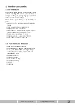
3.  Device properties

3.1  

Intended use

One-channel phase dimmer for brightness control 

of R,L,C including LED retrofit loads. Operates as 

a digital leading and trailing edge phase dimmer 

with automatic load detection.

Please use this product only for its intended pur

-

pose:

• 

As a dimmer for switching and dimming lumi-

naires

•  Solid in dry and clean environment

•  Only approved for indoor use

•  Installation in switch cabinets top-hat rail

, in a 

junction box with insulated enclosure

•  Access is only possible with tools

•  Only operate on 1 phase with 230V AC

•  With a back-up fuse of max. 16A 

3.2  Functions and features

•  DMX retrofit-universal-dimmer 

•  Control via DMX / RDM or push button input

•  Load types: LED retrofit, NV halogen lamps 

with coiled or electronic transformers and 

incandescent lamps

•  Adaptive dimming

•  Manual min-level

•  Load number display

• 

Zero load dimming

•  Soft-Off

•  Fadetime

Summary of Contents for XRD600 REG

Page 1: ...XRD600 REG DMX Retrofit Dimmer Item No 10 252 XRD600 REG Valid from Version Hardware H2 Firmware F2 2 0 Document Date 07 04 2020 Document 10252_MA_en_A4_XRD600REG Manual ...

Page 2: ...g 8 5 1 Measuring procedure AdaptivDIM 8 5 2 Power rating of retrofit dimmers 8 6 Operation via buttons 9 6 1 Device button 9 6 2 Push button input Universal voltage input 9 6 3 Functions push button operation 9 6 4 Set Min level push button 10 6 5 Commissioning and diagnosis 11 7 Start new measument with the device button 12 8 Operation via DMX 13 8 1 Preparation 13 8 2 Assign DMX start address 1...

Page 3: ...ces on the market they comply with the EU directives in the version valid for the respective device Declarations of conformity are available for all products The CE marking is marked on the devices and is shown in the applicable documents Danger The interior and the connectors of the amplifier holds hazardous voltages The unit must only be installed and serviced by a proven electrican specialist i...

Page 4: ...g this maintronic product and the trust you have placed in us We the team of maintronic wish you a lot of fun with this product 2 2 About this Document Due to continuous product development some of the information may not be complete and up to date The information in this document is subject to change without prior notice Please check our website www maintronic de if there is a newer version 2 3 C...

Page 5: ... naires Solid in dry and clean environment Only approved for indoor use Installation in switch cabinets top hat rail in a junction box with insulated enclosure Access is only possible with tools Only operate on 1 phase with 230V AC With a back up fuse of max 16A 3 2 Functions and features DMX retrofit universal dimmer Control via DMX RDM or push button input Load types LED retrofit NV halogen lamp...

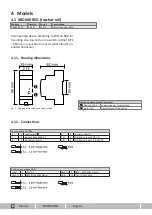
Page 6: ...x or small distributor in sulated enclosure Top connections X1 L 1 Load output N 4 Neutral conductor L 2 Input Voltage 230V AC T 5 Push button input GND N N 3 Neutral conductor T 6 Push button input 12 230V Bottom connections X2 24V 7 24V DC DMX 9 DMX DMX RDM Signal DMX 8 DMX DMX RDM Signal GND 10 24V DMX Shield Operating elements and indicators 1 Device button Commissioning Programming 2 Status L...

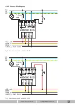
Page 7: ...www maintronic de info maintronic com 7 Fig 3 Connection diagram with push button 24 VDC Fig 2 Connection diagram with push button 230 VAC 4 1 3 Connection diagram ...

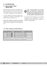
Page 8: ...the rated power 600 VA LED trailing edge approx 70 of the rated power 420 VA LED leading edge approx 20 of the rated power 120 VA As a rule Example 28x 4W rated power LED 20 power factor 135 VA power to be processed Specifi cations depend on the light source used and may vary upwards and downwards When starting up for the first time voltage is ap plied to the device for the first time after instal...

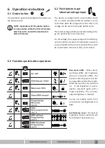
Page 9: ...nd will be recalled at next power up 6 2 Push button input Universal voltage input It is possible to operate and program the device via the device button NOTE Operation with the device button is only possible within the first 60 minutes after Power On and will be deactivated after 60 minutes The device is equipped with a push button input T on which standard 230V AC buttons can be connected Both D...

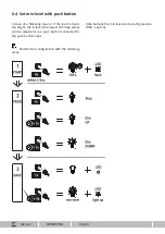
Page 10: ...ively the min level can be configured via DMX see 9 3 In case of a flickering load or if the load remains too bright the in level the lowest dimming value can be adjusted via a push button connected to the push button input Perform the configuration with the following steps ...

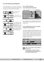
Page 11: ...ible with the select ed dimming mode the system switches to a com patible mode 6 5 2 Determine load no max number of lamps of the same type In order to optimally use the dimmer and to see how many luminaires of the same type can be used it is possible to determine the load number of the luminaire To do this measure with a single luminaire After the measurement the load type is displayed and afterw...

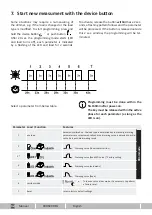
Page 12: ...teristic 3 Dimming curve fixed LED curve Factory setting 4 Dimming curve automatic 5 Dimming curve fixed 6 corridor mode 7 Reset reset to factory default settings Select a parameter from below table To leave a set corridor mode it is necessary to perform a factory reset Programming must be done within the first 60min after power on The key must be released within the active phase for each paramete...

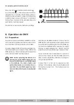
Page 13: ...s device button or push button after 20 seconds the LED il luminates for 2 seconds which shows phase 1 Hold the button pressed in phase 6 is followed by a slightly longer pause until phase 7 is activated During these 2 seconds of the activated phase the push button must be released The dimmer is now reset to the factory settings To operate a device with DMX a DMX512 control ler is required A gatew...

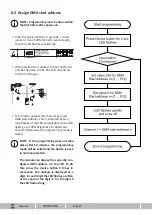
Page 14: ...w DMX start address This is indicated by two long flashes of the LED and possibly connected lights go to 100 brightness for about one second Afterwards the programming mode is exited NOTE If the programming does not take place after 10 minutes the programming mode will be exited and the device is back in normal operation The module can display the currently con figured DMX address via the LED To d...

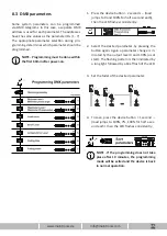
Page 15: ...utton 2 seconds load jumps to 0 and 100 for half a second each then the LED flashes consistently 2 Select the desired parameter by pressing the button again Again a parameter change is in dicated by the output level 0 and 100 as at start The flashing pattern is then indicated by a long light followed by a brief flash of the LED 3 Set the fader of the desired parameter 4 To save press the device bu...

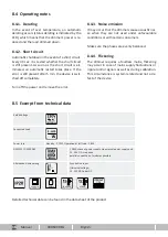
Page 16: ...ke sure the phases are evenly balanced 8 4 4 Flickering The dimmer requires a faultless mains flickering may occur in case of mains supply fluctuations or ripple control signals as well as during calibration This circumstance is system related and not a de fect of the device 8 4 1 Derating In the event of over temperature an automatic derating occurs status derating is indicated by the LED which m...

Page 17: ...lying the operating voltage Standby O During operation with switched off channel Output Switched On OOOOOOOOOOOOOOOOOOOO Switched on the brightness of the LED depends on the output level Receive bus event O O DMX telegram received Operation via push button input OOOO OO DMX input button is pressed mains voltage is present Programming mode OOOOO OOOOO DMX identification display ready for load calib...

Page 18: ...Carl Zeiss Str 10 14 97424 Schweinfurt Germany Tel 49 0 9721 7766 0 Fax 49 0 9721 7766 18 www maintronic de info maintronic de ...

Reviews: