background image

13 

Assembly Instructions 


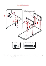
11.


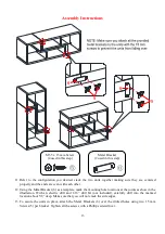
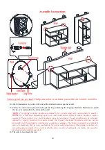
Refer  to  the  configuration  you  desired,  stack  the  two  units  together  making  sure  they  are  centered 
properly and the ends are even with each other. 

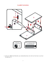
12.


Using the Metal Bracket (6) as a template, mark the mounting hole locations at the joints as show in the 
illustration.  With  an  electric  drill  and  1/16”  drill  bit  (not  included),  carefully  drill  into  the  marked 
location about 5/8” deep. Make sure that you will not crack the side edges. 

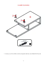
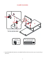
13.


To  secure  the  units  in  place,  attach  the  Metal  Brackets  (6)  over  the  drilled  holes  using  two  15  mm 
Screws (5) per bracket. Tighten all the screws with a Phillips screwdriver. 

Metal Bracket 

(2 used in this step)


5

6

5

6

M3.5 x 15 mm Screw  

(4 used in this step)


Summary of Contents for MS18-D2-1011-02

Page 1: ...y or if parts are missing DO NOT return this item to the store where it was purchased Please call our customer service number and have your instructions and parts list ready to provide the model name part name or factory number 866 942 5362 Pacific Standard Time 8 30 a m 4 30 p m Monday Friday Or visit our web site 24 hours a day 7 days a week for product assistance at www whalenstyle com Or e mai...

Page 2: ...assemble the unit on a sturdy level and non abrasive surface 3 Keep all hardware part out of reach of children MAXIMUM RECOMMENDE D WE IGHT LOADS MAXIMUM LOAD 50 lb 22 7 kg MAXIMUM LOAD 135 lb 61 3 kg THIS UNIT IS INTENDED ONLY FOR USE WITHIN THE MAXIMUM WEIGHTS INDICATED USE WITH HEAVIER THAN THE MAXIMUM WEIGHTS INDICATED MAY RESULT IN INSTABILITY CAUSING POSSIBLE INJURY GENERAL INFORMATIO N TIP ...

Page 3: ...OPERATION HOW THE KNOCK DOWN KD ASSEMBLY SYSTEM WORKS 1 Screw the Cam Bolt into the threaded inserts on the panel Connect both panels together making sure Cam Bolt goes into the pre drilled hole on the end of panel for Cam Lock 2 Insert the Cam Lock into the pre drilled large hole on the panel Make sure the arrow on the face of Cam Lock faces out and points towards Cam Bolt 3 Take a Phillips screw...

Page 4: ...ty 2 D Large Side Panel Qty 2 E Middle Side Panel Qty 2 F Small Side Panel Qty 4 1 Cam Lock 2 Cam Bolt 3 M10 x 40 mm Wood Dowel Qty 32 1 extra Qty 32 1 extra Qty 32 1 extra 4 Cam Lock Cap Qty 32 1 extra 5 M3 5 x 15 mm Screw Qty 4 1 extra 6 Metal Bracket Qty 2 Glue Qty 1 Touch up Pen Qty 1 Tipping Restraint Hardware Kit Qty 2 not included for white finish Inside Plastic Bag Tools required Phillips ...

Page 5: ...he hardware and required parts Assemble the unit on a carpeted floor or the empty carton to avoid any scratch 2 Securely screw the Cam Bolts 2 into the designated small holes on the Shelf Panels A B and C using a Phillips screwdriver 2 x 2 B A C Cam Bolt 28 used in this step ...

Page 6: ...3 Insert two Wood Dowels 3 into the inner holes of each Small Side Panel F and attach it to the Large Shelf Panel A by engaging two Cam Locks 1 1 A F F 3 Cam Lock 4 used in this step M10 x 40 mm Wood Dowel 4 used in this step ...

Page 7: ...bly Instructions 4 Attach one Middle Shelf Panel B onto the Small Side Panels F with four Cam Locks 1 and four Wood Dowels 3 A F F B 3 1 Cam Lock 4 used in this step M10 x 40 mm Wood Dowel 4 used in this step ...

Page 8: ...8 Assembly Instructions 5 Securely screw the Cam Bolts 2 into the designated small holes on the Middle Shelf Panel B Cam Bolt 2 used in this step B 2 2 ...

Page 9: ...ssembly Instructions 6 Attach the Middle Side Panel E to the Middle Shelf Panel B with two Cam Locks 1 and two Wood Dowels 3 Cam Lock 2 used in this step M10 x 40 mm Wood Dowel 2 used in this step B E 3 1 ...

Page 10: ... Assembly Instructions 7 Attach the Large Side Panel D to the Large Shelf Panel A with two Cam Locks 1 and two Wood Dowels 3 A D 3 1 Cam Lock 2 used in this step M10 x 40 mm Wood Dowel 2 used in this step ...

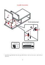
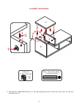
Page 11: ...embly Instructions 8 Attached the Small Shelf Panel C to the Side Panels D and E with four Cam Locks 1 and four Wood Dowels 3 D E C 3 1 Cam Lock 4 used in this step M10 x 40 mm Wood Dowel 4 used in this step ...

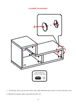
Page 12: ...embly Instructions 9 Put the Cam Lock Caps 4 to the Cam Locks on the Side Panels D E and F to conceal the Cam Locks 10 Repeat the same procedure to assemble the other unit 4 Cam Lock Cap 16 used in this step ...

Page 13: ...t the joints as show in the illustration With an electric drill and 1 16 drill bit not included carefully drill into the marked location about 5 8 deep Make sure that you will not crack the side edges 13 To secure the units in place attach the Metal Brackets 6 over the drilled holes using two 15 mm Screws 5 per bracket Tighten all the screws with a Phillips screwdriver Metal Bracket 2 used in this...

Page 14: ... attached to a wall stud Depending upon your wall construction different anchor hardware maybe required Please contact your local hardware store for assistance Young children can be seriously injured by tipping furniture You must install the Tipping Restraint Hardware with the unit to prevent the unit from tipping causing any accidents or damage The tipping restraints are intended only as a deterr...

Page 15: ...nvironment Extreme temperature and humidity changes can cause fading warping shrinking and splitting of wood It is advised to keep furniture away from direct sunlight as sun may damage the finish Proper care and cleaning at home will extend the life of your purchase Follow these important and helpful tips that will enhance your furniture as it ages A touch up pen has been provided to minimize the ...

Page 16: ......

Page 17: ...rte está faltante no retorne esté producto a la tienda donde lo compró Por favor llame a nuestro departamento de ayuda al cliente teniendo su instructivo y lista de partes para proveer el modelo nombre de parte o el número de fábrica 866 942 5362 Hora estándar del Pacífico 8 30 a m 4 30 p m de Lunes a Viernes O visite nuestra página de Internet 24 horas al día 7 días a la semana para asistencia ww...

Page 18: ... el producto en una superficie fuerte nivelada y libre de abrasivos 3 Mantenga todo el material de ferretería fuera del alcance de niños MÁXIMO PE SO RECOMENDADO MÁXIMA CARGA 50 lb 22 7 kg MÁXIMA CARGA 135 lb 61 3 kg INFORMACIÓN G ENE RAL RECOME NDACIONES Y TRUCO S ESTA UNIDAD DEBE UTILIZARSE CON LOS PESOS MÁXIMOS INDICADOS SI SE EXCEDE EL PESO MÁXIMO PODRIA RESULTAR EN UNA INESTABILIDAD DE LA UNI...

Page 19: ...IJACIÓN CÓMO FUNCIONA LA INSTALACIÓN DE MONTAJE KD 1 Fijar los tornillos de fijación en los orificios pequeños Conectar ambos paneles cerciorandose que los tornillos de fijación entren bien y que estos queden en los orificios al final del panel con tuercas de fijación 2 Inserte las tuercas de fijación en los orificios grandes del panel Hacer que la flecha en la tuerca este apuntando hacia la entra...

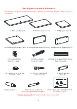
Page 20: ...ano Cant 2 F Módulo lateral pequeño Cant 4 1 Tuerca de fijación 2 Perno de fijación 3 Clavija de madera de M10 x 40 mm Cant 32 1 extra Cant 32 1 extra Cant 32 1 extra 4 Tapón de tuerca de fijación 5 M3 5 x 15 mm Tornillo 6 Soporte metálico Cant 32 1 extra Cant 4 1 extra Cant 2 Pegamento Cant 1 Plumón de retoque Cant 1 Kit de sujeción anti basculante Cant 2 No incluido para el acabado en blanco En ...

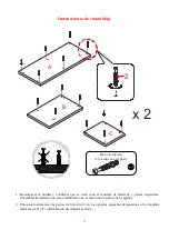
Page 21: ...a y partes requeridas Ensamblar la unidad en un piso alfombrado o en el cartón vacío para evitar rasguños 2 Enrosque fuertemente los pernos de fijación 2 en los agujeros pequeños designados en los módulos laterales A B y C utilizando un desarmador estrella Perno de fijación 28 usados en este paso 2 x 2 B A C ...

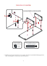
Page 22: ...clavijas de madera 3 en los agujeros interiores de cada módulo lateral pequeño F y únalo a la balda grande A uniendo dos tuercas de fijación 1 1 A F F 3 Tuerca de fijación 4 usadas en este paso Clavija de madera de M10 x 40 mm 4 usadas en este paso ...

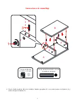
Page 23: ... 4 Una la balda mediana B a los módulos laterales pequeños F con cuatro tuercas de fijación 1 y cuatro clavijas de madera 3 A F F B 3 1 Tuerca de fijación 4 usadas en este paso Clavija de madera de M10 x 40 mm 4 usadas en este paso ...

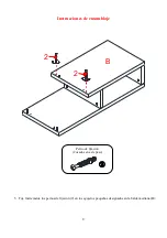
Page 24: ...8 Instrucciones de ensamblaje 5 Fije fuertemente los pernos de fijación 2 en los agujeros pequeños designados en la balda mediana B B 2 2 Perno de fijación 2 usados en este paso ...

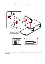
Page 25: ...amblaje 6 Una el modulo lateral mediano E a la balda mediana B con dos tuercas de fijación 1 y dos clavijas de madera 3 B E 3 1 Tuerca de fijación 2 usadas en este paso Clavija de madera de M10 x 40 mm 2 usadas en este paso ...

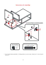
Page 26: ...nsamblaje 7 Una el módulo lateral grande D a la balda grande A con dos tuercas de fijación 1 y dos clavijas de madera 3 A D 3 1 Tuerca de fijación 2 usadas en este paso Clavija de madera de M10 x 40 mm 2 usadas en este paso ...

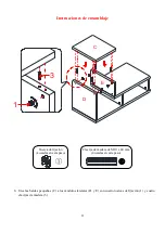
Page 27: ...je 8 Una las baldas pequeñas C a los módulos laterales D y E con cuatro tuercas de fijación 1 y cuatro clavijas de madera 3 D E C 3 1 Tuerca de fijación 4 usadas en este paso Clavija de madera de M10 x 40 mm 4 usadas en este paso ...

Page 28: ...aje 9 Coloque el embellecedor 4 en las tuercas de fijación de los módulos laterales D E y F para ocultar las tuercas de fijación 10 Repita el mismo procedimiento para ensamblar la otra unidad Embellecedor 16 usados en este paso 4 ...

Page 29: ...se muestra en la ilustración Con un taladro y una broca de 1 16 no incluidos taladrar cuidadosamente en los lugares marcados a una profundidad de 5 8 Asegurar de que no agriete los bordes laterales 13 Para asegurar las unidades en su lugar adjuntar los soportes metálicos 6 sobre los agujeros perforados usando los tornillos de 15 mm 5 por soporte Apretar todos los tornillos con el desarmador de est...

Page 30: ...s para una pared de tacos de madera Necesita ser adjuntado a un taco de madera Dependiendo de la para diferentes anclas pueden ser requeridas Por favor contacte su tienda de ferretería local para asistencia Niños pequeños pueden resultar lastimados por muebles inclinados Debe instalar el juego de restricción de movimiento con la unidad en función para prevenir la inclinación de la unidad causando ...

Page 31: ...se contraigan o que la madera se raje Es recomendable mantener la unidad lejos del sol directo ya que puede dañar el acabado Cuidados adecuados y limpieza pueden extender la vida útil de su unidad Siga estas recomendaciones y mantendrá su mueble en buenas condiciones de uso por muchos años Un plumón de retoque se ha proporcionado para minimizar las pequeños daños o rayones que pueden haber ocurrid...

Page 32: ......

Reviews: