background image

IMPORTANT 


Before  you  begin:

  Open,  identify  and  count  all  parts  prior  to  assembly.  Lay  out  parts  on  a  flat  and  non-

abrasive surface. You will need the parts identified on page 4 and 5 of this instruction manual. 
 

NOTE:

  IT  IS  VERY  IMPORTANT  TO  USE  GLUE  WITH  DOWELS.  EXCESS  GLUE  CAN  BE  WIPED 

OFF WITH DAMP CLOTH. 
 
Insert the Dowel at least half way by tapping lightly with a rubber mallet, IF NECESSARY. 


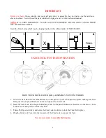
CAM LOCK SYSTEM OPERATION 


HOW THE KNOCK DOWN (KD) ASSEMBLY SYSTEM WORKS 


1.


Screw the Cam Bolt into the threaded inserts on the panel. Connect both panels together; making sure Cam 
Bolt goes into the pre-drilled hole on the end of panel for Cam Lock. 

2.


Insert the Cam Lock into the pre-drilled large hole on the panel. Make sure the arrow on the face of Cam 
Lock faces out and points towards Cam Bolt. 

3.


Take a Phillips screwdriver and rotate the Cam Lock clockwise to lock the Cam Bolt in place. 

4.


Plug the Cam Lock Cover into the cross slot of the Cam Lock to conceal the Cam. 


You are now ready to assemble the fireplace. 


X

X

FINAL

1

2

4

3


Summary of Contents for Entertainment Center

Page 1: ...ve any questions regarding assembly or if parts are missing DO NOT return this item to the store where it was purchased Please call our customer service number and have your instructions and parts lis...

Page 2: ...MAXIMUM LOAD 50 lb 22 7 kg FITS UP TO MOST 55 FLAT PANEL TVs MAXIMUM LOAD 135 lb 61 3 kg THIS UNIT IS NOT INTENDED FOR USE WITH CRT TVS USE ONLY WITH FLAT PANEL TVS AND AUDIO VIDEO EQUIPMENT MEETING R...

Page 3: ...RATION HOW THE KNOCK DOWN KD ASSEMBLY SYSTEM WORKS 1 Screw the Cam Bolt into the threaded inserts on the panel Connect both panels together making sure Cam Bolt goes into the pre drilled hole on the e...

Page 4: ...assembly A Top Panel Qty 1 B Bottom Panel Qty 1 C Left Side Panel Qty 1 D Right Side Panel Qty 1 E Large Divider Panel Qty 1 F Small Divider Panel Qty 1 G Large Fixed Shelf Qty 1 H Back Panel Qty 1 I...

Page 5: ...ood Dowel 4 M6 x 30 mm Wood Dowel Qty 8 1 extra Qty 40 2 extra 5 5 16 x 40 mm Bolt 6 Lock Washer 7 Flat Washer Qty 8 1 extra Qty 8 1 extra Qty 8 1 extra 8 Plastic Cap Qty 4 1 extra 9 Shelf Pin Qty 16...

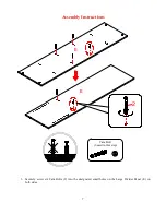
Page 6: ...re and required parts Assemble the unit on a carpeted floor or the empty carton to avoid any scratch 2 Securely screw the Cam Bolts 2 into the designated small holes on the Bottom Panel B and the Side...

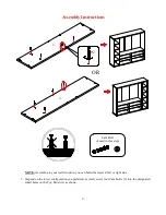
Page 7: ...7 Assembly Instructions 3 Securely screw six Cam Bolts 2 into the designated small holes on the Large Divider Panel E on both sides Cam Bolt 6 used in this step 2 E E...

Page 8: ...8 Assembly Instructions 4 Securely screw four Cam Bolts 2 into the designated small holes on the Large Fixed Shelf G on both sides Cam Bolt 4 used in this step 2 G G...

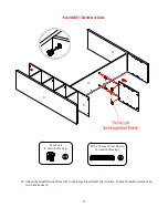
Page 9: ...ur wall structure you can build the tower at left or right side 5 Depend on the tower configuration you preferred securely screw four Cam Bolts 2 into the designated small holes on the Top Panel A as...

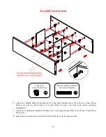
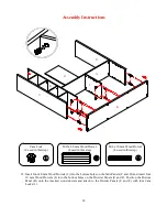
Page 10: ...to page 3 on Cam Lock system operation supplement 7 Attach two Top Bottom Small Fixed Shelves J to the Large Divider Panel E with four 30 mm Wood Dowels 4 8 Repeat the same procedure to attach the Le...

Page 11: ...arge Fixed Shelf G to the Large Divider Panel E and Right Side Panel D with four 30 mm Wood Dowels 4 and four Cam Locks 1 G 1 1 4 4 C E D UP 1 1 1 1 4 D C E G 4 1 1 Cam Lock 4 used in this step OR M6...

Page 12: ...Instructions 10 Attach the Small Divider Panel F to the Large Fixed Shelf G with two 30 mm Wood Dowels 4 and two Cam Locks 1 UP C D G F E 1 4 Cam Lock 2 used in this step M6 x 30 mm Wood Dowel 2 used...

Page 13: ...13 Assembly Instructions 11 Attach the Back Panel H to the Large Fixed Shelf G with two 30 mm Wood Dowels 4 as shown UP 4 G F D C E H M6 x 30 mm Wood Dowel 2 used in this step...

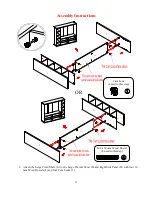
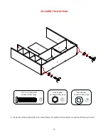
Page 14: ...Wood Dowels 4 into the bottom holes on the Divider Panels E and F Position the Bottom Panel B onto the inserted wood dowels and attach to the Divider Panels E and F with four Cam Locks 1 Cam Lock 4 u...

Page 15: ...Fasten the Bottom Panel B to the Side Panels C and D with four Bolts 5 and four Washers 6 and 7 Lock Washer 4 used in this step Flat Washer 4 used in this step B UP C E G F D H 5 6 7 6 7 5 5 16 x 40...

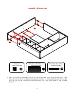
Page 16: ...wels 4 into the top holes on the Large Divider Panel E and the Back Panel H Position the Top Panel A onto the inserted wood dowels and attach to the Large Divider Panel E with two Cam Locks 1 Cam Lock...

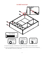
Page 17: ...16 Cover the countersunk holes on Top Panel A by inserting four Plastic Caps 8 Gently tap the Plastic Cap with a rubber mallet to ensure they are fully seated B UP E G F D H C A 5 6 7 8 Plastic Cap 4...

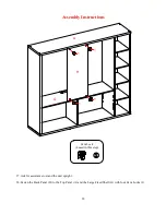
Page 18: ...embly Instructions 17 Ask for assistance to stand the unit upright 18 Fasten the Back Panel H to the Top Panel A and the Large Fixed Shelf G with four Cam Locks 1 Cam Lock 4 used in this step A H G 1...

Page 19: ...the compartments Make sure you place the four Shelf Pins in the same level so the shelf is not tilted Tilt and rest the Adjustable Shelves K and L onto the Shelf Pins 9 with the end notches of the Sh...

Page 20: ...panel television directly on the console 20 Remove the paper backing from the Stop Rail M then properly align the Stop Rail with the top edge of the stopper template on the Large Fixed Shelf G Press...

Page 21: ...the unit and the wall NOTE Young children can be seriously injured by tipping furniture You must install the Tipping Restraint Hardware with the unit to prevent the unit from tipping causing any acci...

Page 22: ...led environment Extreme temperature and humidity changes can cause fading warping shrinking and splitting of wood It is advised to keep furniture away from direct sunlight as sun may damage the finish...

Page 23: ...erca del ensamble o si alguna parte est faltante no retorne este producto a la tienda donde lo compr Por favor llame a nuestro departamento de ayuda al cliente teniendo su instructivo y lista de parte...

Page 24: ...RGA M XIMA 50 lb 22 7 kg PARA MAYOR A DE LAS TELEVISIONES DE PANTALLA PLANA DE 55 pulgadas CARGA M XIMA 135 lb 61 3 kg PONER LA TV DETR S DEL TOPE ESTA UNIDAD NO DEBE UTILIZARSE CON TELEVISIONES CRT O...

Page 25: ...E FIJACI N C MO FUNCIONA LA INSTALACI N DE MONTAJE KD 1 Fijar los tornillos de fijaci n en los orificios peque os Conectar ambos paneles cerciorandose que los tornillos de fijaci n entren bien y que e...

Page 26: ...erior Cant 1 B Panel inferior Cant 1 C Panel lado izquierdo Cant 1 D Panel lateral derecho Cant 1 E Panel divisor grande Cant 1 F Panel divisor peque o Cant 1 G Repisa fija grande Cant 1 H Panel poste...

Page 27: ...de madera Cant 8 1 extra Cant 40 2 extra 5 Tornillo de 5 16 x 40 mm 6 Arandela presi n 7 Arandela plana Cant 8 1 extra Cant 8 1 extra Cant 8 1 extra 8 Tapa de pl stico Cant 4 1 extra 9 Perno de repis...

Page 28: ...partes requeridas Ensamblar la unidad en un piso alfombrado o en el cart n vac o para evitar rasgu os 2 Coloque los tornillos de fijaci n 2 en los orificios peque os designados en el panel inferior B...

Page 29: ...7 Instrucciones de ensamble 3 Poner seis tornillos de fijaci n 2 en los agujeros peque os designados en el divisor grande E en ambos lados Tornillo de fijaci n 6 usados en este paso 2 E E...

Page 30: ...8 Instrucciones de ensamble 4 Poner cuatro tornillos de fijaci n 2 en los agujeros peque os designados en la repisa fija grande G en ambos extremos Tornillo de fijaci n 4 usados en este paso 2 G G...

Page 31: ...construir la torre en el lado izquierdo o derecho 5 Depender de la configuraci n de torre que prefer as fijar con seguridad cuatro tornillos de fijaci n 2 en los orificios peque os designados en el p...

Page 32: ...to de la operaci n del sistema de fijaci n 7 Coloque dos repisas fijas superior inferior peque as J al panel divisor grande E con cuatro pernos de 30 mm de madera 4 8 Repetir el mismo procedimiento pa...

Page 33: ...G al panel divisor grande E y el panel lateral derecho D con cuatro pernos de 30 mm de madera 4 y cuatro tuercas de fijaci n 1 G 1 1 4 4 C E D UP 1 1 1 1 4 D C E G 4 1 1 Tuerca de fijaci n 4 usados e...

Page 34: ...a el panel divisor peque o F a la repisa fija grande G con dos pernos de 30 mm espigas de madera 4 y dos tuercas de fijaci n 1 UP C D G F E 1 4 Tuerca de fijaci n 2 usados en este paso Perno M6 x 30 m...

Page 35: ...13 Instrucciones de ensamble 11 Adjuntar el panel posterior H a l repisa fija grande G con dos pernos de 30 mm de madera 4 como se muestra UP 4 G F D C E H M6 x 30 mm de madera 2 usados en este paso...

Page 36: ...e madera 4 en los orificios inferiores en los paneles divisores E y F Coloque el panel inferior B sobre los pernos de madera insertados y se unen a los paneles divisores E y F con cuatro tuercas de fi...

Page 37: ...anel inferior B a los paneles laterales C y D con cuatro tornillos 5 y cuatro arandelas 6 y 7 Arandela presi n 4 usados en este paso Arandela plana 4 usados en este paso B UP C E G F D H 5 6 7 6 7 5 T...

Page 38: ...a 4 en los orificios superiores en el panel divisor grande E y el panel posterior H Coloque el panel superior A sobre los pernos de madera insertados y adjuntar al panel divisor grande E con dos tuerc...

Page 39: ...en el panel superior A mediante la inserci n de cuatro tapas de pl stico 8 Golpear suavemente la tapa de pl stico con un martillo de goma para asegurar que est n completamente insertados Tapa pl stic...

Page 40: ...de ensamble 17 Posicionar la unidad en posici n vertical 18 Fije le panel posterior H al panel superior A y la repisa fija grande G con 4 tuercas de fijaci n 1 Tuerca de fijaci n 4 usados en este pas...

Page 41: ...g rese de colocar los cuatro pernos de repisa en el mismo nivel por lo que la repisa no quede inclinada Incline y descanse las repisas ajustables K y L en los pernos de repisa 9 cuidando que las muesc...

Page 42: ...plana directamente en la consola 20 Retire el papel protector del riel tope M y luego alinear correctamente el riel tope con el borde superior de la plantilla del tope en la repisa fija grande G Presi...

Page 43: ...a la consola y a la pared NOTA Ni os peque os pueden resultar lastimados por muebles inclinados Debe instalar el herraje de restricci n de movimiento con la unidad en funci n para prevenir la inclina...

Page 44: ...que se contraigan o que la madera se parta Es recomendable mantener la unidad lejos del sol directo ya que puede da ar el acabado Los cuidados adecuados y limpieza pueden extender la vida til de su u...

Reviews: