background image

06-2016

01   EXPLOSIONADO

PR-360

5

86

51

B

28

37

73

10

L

26

50

123

66

P

N

J

47

72

84

E

4

106

A

26

27

45

130

46

133 K

49

57

36

125

42

77

25

126

S

119

58

69 70

103

94

102

47

T

65

95

32

19

91

76

44

132

83

100

43

131 Q

127

115

110

107

4

112

8

116

55

69

85

70

6

54

7

59 29

75

60

12

75

23

8

2

112

124

5

20

15

16

1

35

52

C

127

117

99

80

48

Summary of Contents for PR-360

Page 1: ...553750 PR 360 1 ESPA OL 1 2 ENGLISH 12 3 FRAN AIS 22 4 DEUTSCH 28 P I Coll de la Manya Jaume Ferr n s n E 08400 Granollers Barcelona SPAIN 34 93 849 18 22 17 54 Fax 34 93 849 71 76 www mainca com E ma...

Page 2: ...cer los pedidos de recambios de material el ctricos rogamos indiquen la marca y referencia completa tomada del aparato IMPORTANT Pour les comandes de mat riel lectrique indiquez s il vous plait la mar...

Page 3: ...las caracter sticas t cnicas indicadas en la placa de la m quina WARNING The machine must be connected to a power breaker combined overload and earth leakage detector rated as per the details on the m...

Page 4: ...ci n B ver f gura 1 Esta particularidad hace posible ajustar la altura de conexi n del equipo a cualquier embutidora MAINCA mediante la Maneta graduaci n B Una vez ajustada la altura de conexi n del e...

Page 5: ...on el Eje pist n G y los 4 Pomos H correctamente apretados 3 Cargue el producto en el cilindro de la embutidora y cierre a continuaci n la tapa del cilindro desplazando a su vez el equipo ya unido a s...

Page 6: ...ntos de utilizaci n de ste se haga en posici n manual combinando rodillera embutidora y Pulsador Hay que recordar que se trata de un equipo semi autom tico y la habilidad del usuario alimentando a tra...

Page 7: ...pantallas El Paro de emergencia N se utiliza para parar el ciclo de trabajo ver figura 2 LIMPIEZA 1 Pulsar el Pulsador de paro de emergencia N 2 Desmontar el embudo L ver fig 4 3 Desmontar los 4 pomos...

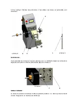
Page 8: ...eutro y una esponja Evite el uso de elementos met licos en el proceso de limpieza ver fig 5 5 Para la limpieza del interior de los embudos es necesario el cepillo espiral S ver fig 6 MANTENIMIENTO Es...

Page 9: ...imo 62 dB A SEGURIDAD El MAINCA PR 360 dispone de 2 elementos de seguridad El primero es el paro de emergencia N situado en su panel de mandos que impide el funcionamiento del equipo El segundo es un...

Page 10: ...y el cono blando X para el uso de tripa sint tica celulosa o col geno y tambi n para el uso de tripa natural a adiendo la opci n del doble embudo que corresponda Una vez acoplado volver a roscar los...

Page 11: ...ra ello aflojar la empu adura transversal 4 y desplazar la parte del soporte de los rodillos verticalmente MUY IMPORTANTE El centrado de los rodillos no debe ser perfecto es imprescindible que queden...

Page 12: ...io aumenta la separaci n y en sentido antihorario la disminuye ver fig 13 Por ltimo el mecanismo para proceder al cambio del embudo H y o cargar la tripa nuevamente s lo hay que girar 90 el conjunto d...

Page 13: ...activated via the adjustment lever B See figure 1 This feature makes it possible to adjust the height of the machine connection to any MAINCA sausage stuffer using the adjustment lever B After the he...

Page 14: ...s stuffers If you intend to use this twist linker with a non MAINCA filler you need to replace our nozzle nut by the one used on your filler Unscrew the feeding tube to simply replace the nozzle nut 2...

Page 15: ...a soft dough using a bigger nozzle see fig 3 5 Install the most suitable nozzle size L using the nozzle nut K and use the most appropriate rubber cone according to your casing calibre There are differ...

Page 16: ...g if you don t want to break the casing when twisting Adjust this setting depending on the type of casing you are using We recommend to twist natural casing at low speed between 800 to 1000rpm collage...

Page 17: ...e equipped with reverse thread nozzle nut Machines with nozzle turning Counter clockwise are equipped with regular thread nozzle nut 9 LANGUAGE SELECTION This setting allows you to change the language...

Page 18: ...d with warm water neutral soap and a sponge Avoid using metal items during the cleaning process see fig 5 5 To clean inside the nozzles use the spiral brush S supplied with each machine see fig 6 MAIN...

Page 19: ...most 62 dB A SAFETY The MAINCA PR 360 has two safety elements The first is the emergency stop button N located on the control panel that stops the machine from running The second is the lid sensor U t...

Page 20: ...n to the PR 250 using the front lid knobs R Unscrew the 2 knobs hook up the automatic hand to the threaded pins and screw the knobs on tight by hand see fig 10 Once the automatic hand is duly installe...

Page 21: ...see fig 12 The gap between rollers 3 should not be aligned with the center of the silicon tip X We recommend to align the bottom of the upper roller 3 with the center of the silicon tip X to ensure th...

Page 22: ...silicon tip X to ensure the rollers will hold the casing tight enough to be twisted see fig 13 Both rollers can be independently moved aside by hand 90 to ease the reload of casing or change of the s...

Page 23: ...tion B voir sch ma 1 Cette particularit permet de r gler la hauteur de connexion de la machine toute farcisseuse MAINCA avec la manette d ajustement B Apr s avoir ajust la hauteur du raccordement de l...

Page 24: ...ont bien serr s 3 Chargez le produit dans le cylindre de l emboutisseuse puis fermez le couvercle du cylindre en d pla ant la fois l quipement qui est d j uni celle ci 4 Ajustez la portion avec le bou...

Page 25: ...l s agit d un quipement semi automatique et que l habilet de l utilisateur lors de l alimentation par l emboutisseuse en portionnement torsion est aussi importante que n cessaire PARAM TRES DE R GLAGE...

Page 26: ...up rieure du couvercle frontal O et enlevez le Piston en utilisant la cl P voir sch ma 4 4 D vissez le porte entonnoir D de l emboutisseuse et la fermeture Q et le retirer vers la gauche pour pouvoir...

Page 27: ...imordial de conserver toujours graiss s avec un lubrifiant adapt aux aliments la bague T et le piston ou Piston portionneuse F voir sch ma 7 NIVEAU SONORE Le niveau de pression acoustique continu quiv...

Page 28: ...Le premier est l arr t d urgence N situ dans le panneau de contr le et qui emp che le fonctionnement de l quipement Le second est un capteur de position U de pr sence du couvercle frontal O qui emp ch...

Page 29: ...ebel B s Abb 1 verstellt werden kann Durch diese Besonderheit kann die Anschlussh he des Ger ts f r jeden Wurstf ller MAINCA mit dem Hebel B eingestellt werden Nachdem die Anschlussh he des Ger ts f r...

Page 30: ...ezogen sind 3 F llen Sie die Masse in den Zylinder des Wurstf llers schlie en Sie danach den Zylinderdeckel indem Sie das mit diesem bereits verbundene Ger t verschieben 4 Stellen Sie die Portionsgr e...

Page 31: ...er zu kombinieren Es muss daran erinnert werden dass es sich bei der Vorrichtung um ein halbautomatisches Ger t handelt wobei die Geschicklichkeit des Benutzers beim Bef llen des Wurstf llers und beim...

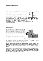
Page 32: ...deckung O des Portionierers s Abb 4 entfernen Sie die vordere Abdeckung O und entfernen Sie den Kolben mit dem Schl ssel P s Abb 4 4 Schrauben Sie die Trichterhalterung D von dem Wurstf ller und dem V...

Page 33: ...G Es ist u erst wichtig dass der Ring T und der Portionierkolben F st ndig mit nahrungsmitteltauglichem Schmiermittel einge lt sind s Abb 7 GER USCHPEGEL Der Dauerger uschpegel entspricht dem gewichte...

Page 34: ...cherheitsvorrichtungen Die erste ist der Not Halt Knopf N der sich auf seinem Bedienungsfeld befindet und die Vorrichtung abschaltet Die zweite ist ein Positionssensor U auf der vorderen Abdeckung O d...

Page 35: ...r H mit Silikont lle X zum Abdrehen von Kunstdarm auf Cellulose oder Collagenbasis und von Naturdarm entwickelt f r den das entsprechende Doppel F llrohr angebracht werden kann Nach dem Aufsetzen des...

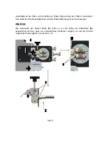
Page 36: ...en seitlichen Drehknauf 4 l sen und die Rollenhalterung auf und ab bewegen WICHTIG Die Unterseite der oberen Rolle 3 sollte so an der Mitte der Silikont lle X ausgerichtet werden dass ein einwandfreie...

Page 37: ...um den Abstand zu vergr ern und entgegen dem Uhrzeigersinn um ihn zu verkleinern siehe Abb 13 Zum Austauschen des F llrohrs H bzw Aufschieben des Darms muss die Rollenhalterung lediglich um 90 nach li...

Page 38: ...hen try same size as casing When twisting natural casing you need to add the optional outer sleeve to avoid the casing rolls up with the twisting nozzle and breaks See above photos of outer sleeve Twi...

Page 39: ...66 P N J 47 72 84 E 4 106 A 26 27 45 130 46 133 K 49 57 36 125 42 77 25 126 S 119 58 69 70 103 94 102 47 T 65 95 32 19 91 76 44 132 83 100 43 131 Q 127 115 110 107 4 112 8 116 55 69 85 70 6 54 7 59 29...

Page 40: ...78 39 M 114 128 22 14 11 76 95 109 67 9 5 122 24 121 U 18 9 06 2016 02 EXPLOSIONADO PR 360 113 85 63 53 33 62 H 108 88 30 56 F 101 D 92 93 105 104 79 64 120 112 40 17 R 118 41 61 I 111 98 97 3 74 71 8...

Page 41: ...06 2016 03 OPCION BRAZO MECANICO PR 360 177 189 192 176 171 186 193 187 171 188 175 172 182 170 178 185 184 183 181 183 194 196 174 179 195 190 191 193 180 173 168 197 185 199 169...

Page 42: ...04 OPCION TRANSFORMADOR A 110v 60Hz 06 2016 PR 360 167 166 165 164...

Page 43: ...06 2016 05 OPCION EMBUDOS DOBLES EMBUDOS CONOS PR 360 160 25 26 27 162 161 200 201 202 203 204 205 206 207 208 209 210 211 212 213 214 215 216 217 218 219 220 221 150 151 152 153 154 155 156...

Page 44: ...rio 5PR44164 ROSCA IZQ 45 5PR31315 ROSCA IZQ 42 5PR44326 ROSCA DER 43 5PR44327 ROSCA DER 44 HS Giro Antihorario 5PR44144 ROSCA DER 133 5PR31310 ROSCA DER 130 5PR44405 ROSCA IZQ 131 5PR44404 ROSCA IZQ...

Page 45: ...DA EJE PISTON 1 23 6CT080725 CHAVETA DIN6885A 08x07x25 2 24 5PR44324 COLUMNA TAPA FRONTAL PR 360 4 25 5PR44367 CJTO EMBUDO 12 250mm 1 26 5PR44370 CJTO EMBUDO 15 285mm 1 27 5PR44373 CJTO EMBUDO 17 285m...

Page 46: ...L C MUELLE I RETEN 35 47 7 RDL M INOX 2 ROD RIGIDO A BOLAS 16007 ZZ 2 RODAMIENTO 61806 ISB ZZ 1 69 6RT354707 70 6RD16007ZZ 71 6RD61806ZZ 72 4SR60RGNY GRUPO RUEDA 60 POL ROJO s fren 2 73 4SR60RGNYF GRU...

Page 47: ...912I0820 TORNILLO ALLEN 08x20 INOX 4 116 6912I0825 TORNILLO ALLEN 08x25 INOX 4 117 6PTNV3W PANTALLA TACTIL OMRON NV3W MG20 V1 1 118 6912I0535 TORNILLO ALLEN M5x35 INOX 4 119 6MTCCB1013 TORNILLO MTCCB...

Page 48: ...1 188 5PR44096 1 1 1 2 1 2 2 1 1 1 189 5XX41368P 190 6TO1215 191 6007I0618 192 6007I1045 193 6125I18 194 61481I0316 195 6AR081210I 196 6TO0802 197 5PR44444 EJE RODILLO FRONTAL EJE RODILLO SUPERIOR MM...

Page 49: ...08 5PR43839 CONO TROMPETA BLANDO 12x 23 1 209 5PR43887 CONO TROMPETA BLANDO 12x 24 1 210 5PR44046 CONO TROMPETA BLANDO 15x 25 1 211 5PR43841 CONO TROMPETA BLANDO 15x 26 1 212 5PR43918 CONO TROMPETA BL...

Page 50: ...otores 25 04 2017 3 Control 25 04 2017 4 Control 25 04 2017 1 Lista de componentes 25 04 2017 1 Lista de Bornes 25 04 2017 Proyecto N Hojas Fecha Cliente PR360 110 V3 Ref Cliente Alimentaci n Intensid...

Page 51: ...B7 4 B3 3 C1 3 A5 3 A5 3 A5 3 A5 2 B4 3 C1 2 B7 3 A6 3 B3 2 A1 2 A1 2 A1 ECN Fecha Nombre Fecha Ref Cliente Hoja 01 Proyecto Cliente Hojas 04 PR360 110 V3 25 04 2017 1 N 2 N 1 5 X1 8 8 X1 6 6 A2 X1 6...

Page 52: ...L3 CN1 P B1 CN2 CNB CNA CW CW CCW CCW 24IN S ON COM CLR CLR PCO PCO ALM BK COIN 1 2 3 4 5 6 7 8 9 10 11 12 13 14 10 6 5 3 FG 1 gris rojo x 3 CW1 gris negro x 3 blanco rojo x 3 CCW1 blanco negro x 3 X...

Page 53: ...nicial pist n B2 Detector tapa frontal S2 Pulsador de marcha ECN Fecha Nombre Fecha Ref Cliente Hoja 03 Proyecto Cliente Hojas 04 PR360 110 V3 25 04 2017 PE X1 4 X1 5 Analog Input U1 2 CW1 Giro sentid...

Page 54: ...V3 Control Lugar por Defecto A 1 D5 3 A6 3 C3 A2 ECN Fecha Nombre Fecha Ref Cliente Hoja 04 Proyecto Cliente Hojas 04 PR360 110 V3 25 04 2017 Omron CP1W CIF01 DB9M X1 6 X1 5 PE 3 2 4 5 9 gy bk gr br w...

Page 55: ...Omron R88A CRGB001 5CR E 1 00 A 2 C5 U2 Cable control 1m Omron R7A CPB001 S 1 00 A 2 C5 U2 Cable de alimentaci n Omron R7A CLB002 S2 1 00 A 3 C1 A1 Controlador 8 ent 6 sal Omron CP1L L14DT D 1 00 A 4...

Page 56: ...orne Puentes Componente Cantidad 8 1 1 C5 2 1 D5 3 1 C6 4 1 D5 5 1 C6 6 1 D5 7 1 C6 8 1 D4 ECN Fecha Nombre Fecha Ref Cliente 25 04 2017 Proyecto Cliente Hoja 01 Hojas 01 Enginy Autom tica SCP Collsab...

Page 57: ...or connection 25 04 2017 3 Control 25 04 2017 4 Control 25 04 2017 1 Parts list 25 04 2017 1 Terminal List 25 04 2017 Project N Sheets Date Customer PR360 110 V3 Customer Ref Main Supply Max Intensity...

Page 58: ...B7 4 B3 3 C1 3 A5 3 A5 3 A5 3 A5 2 B4 3 C1 2 B7 3 A6 3 B3 2 A1 2 A1 2 A1 ECN Date Name Date Customer Ref Sheet 01 Project Customer Next 04 PR360 110 V3 25 04 2017 1 N 2 N 1 5 X1 8 8 X1 6 6 A2 X1 6 X1...

Page 59: ...A L1 L3 CN1 P B1 CN2 CNB CNA CW CW CCW CCW 24IN S ON COM CLR CLR PCO PCO ALM BK COIN 1 2 3 4 5 6 7 8 9 10 11 12 13 14 10 6 5 3 FG 1 gray red x 3 CW1 gray black x 3 white red x 3 CCW1 white black x 3 X...

Page 60: ...n detector B2 Front cover detector S2 Start pushbutton ECN Date Name Date Customer Ref Sheet 03 Project Customer Next 04 PR360 110 V3 25 04 2017 PE X1 4 X1 5 Analog Input U1 2 CW1 Clock wise rotation...

Page 61: ...10 V3 Control Default place A 1 D5 3 A6 3 C3 A2 ECN Date Name Date Customer Ref Sheet 04 Project Customer Next 04 PR360 110 V3 25 04 2017 Omron CP1W CIF01 DB9M X1 6 X1 5 PE 3 2 4 5 9 gy bk gr br wh OM...

Page 62: ...5CR E 1 00 A 2 C5 U2 Control cable 1m Omron R7A CPB001 S 1 00 A 2 C5 U2 Power supply cable Omron R7A CLB002 S2 1 00 A 3 C1 A1 8 inputs and 6 outputs controller Omron CP1L L14DT D 1 00 A 4 B4 A2 Touch...

Page 63: ...inal Bridge Part Quantity 8 1 1 C5 2 1 D5 3 1 C6 4 1 D5 5 1 C6 6 1 D5 7 1 C6 8 1 D4 ECN Date Name Date Customer Ref 25 04 2017 Project Customer Sheet 01 Next 01 Enginy Autom tica SCP Collsabadell 68 0...

Page 64: ...otores 25 04 2017 3 Control 25 04 2017 4 Control 25 04 2017 1 Lista de componentes 25 04 2017 1 Lista de Bornes 25 04 2017 Proyecto N Hojas Fecha Cliente PR360 230 V3 Ref Cliente Alimentaci n Intensid...

Page 65: ...C1 3 A5 3 A5 3 A5 3 A5 2 B4 3 C1 2 B7 3 A6 3 B3 2 A1 2 A1 2 A1 ECN Fecha Nombre Fecha Ref Cliente Hoja 01 Proyecto Cliente Hojas 04 PR360 230 V3 25 04 2017 1 N 2 N X1 8 8 X1 6 6 A2 X1 6 X1 4 4 C B2 X...

Page 66: ...L3 CN1 P B1 CN2 CNB CNA CW CW CCW CCW 24IN S ON COM CLR CLR PCO PCO ALM BK COIN 1 2 3 4 5 6 7 8 9 10 11 12 13 14 10 6 5 3 FG 1 gris rojo x 3 CW1 gris negro x 3 blanco rojo x 3 CCW1 blanco negro x 3 X...

Page 67: ...nicial pist n B2 Detector tapa frontal S2 Pulsador de marcha ECN Fecha Nombre Fecha Ref Cliente Hoja 03 Proyecto Cliente Hojas 04 PR360 230 V3 25 04 2017 PE X1 4 X1 5 Analog Input U1 2 CW1 Giro sentid...

Page 68: ...V3 Control Lugar por Defecto A 1 D4 3 A6 3 C3 A2 ECN Fecha Nombre Fecha Ref Cliente Hoja 04 Proyecto Cliente Hojas 04 PR360 230 V3 25 04 2017 Omron CP1W CIF01 DB9M X1 6 X1 5 PE 3 2 4 5 9 gy bk gr br w...

Page 69: ...2 C5 U2 Cable control 1m Omron R7A CPB001 S 1 00 A 2 C5 U2 Cable de alimentaci n Omron R7A CLB002 S2 1 00 A 3 C1 A1 Controlador 8 ent 6 sal Omron CP1L L14DT D 1 00 A 4 B4 A2 Pantalla t ctil Omron NV3W...

Page 70: ...orne Puentes Componente Cantidad 8 1 1 C4 2 1 D4 3 1 C5 4 1 D4 5 1 C5 6 1 D4 7 1 C5 8 1 D4 ECN Fecha Nombre Fecha Ref Cliente 25 04 2017 Proyecto Cliente Hoja 01 Hojas 01 Enginy Autom tica SCP Collsab...

Page 71: ...otores 25 04 2017 3 Control 25 04 2017 4 Control 25 04 2017 1 Lista de componentes 25 04 2017 1 Lista de Bornes 25 04 2017 Proyecto N Hojas Fecha Cliente PR360 230 V3 Ref Cliente Alimentaci n Intensid...

Page 72: ...C1 3 A5 3 A5 3 A5 3 A5 2 B4 3 C1 2 B7 3 A6 3 B3 2 A1 2 A1 2 A1 ECN Fecha Nombre Fecha Ref Cliente Hoja 01 Proyecto Cliente Hojas 04 PR360 230 V3 25 04 2017 1 N 2 N X1 8 8 X1 6 6 A2 X1 6 X1 4 4 C B2 X...

Page 73: ...L3 CN1 P B1 CN2 CNB CNA CW CW CCW CCW 24IN S ON COM CLR CLR PCO PCO ALM BK COIN 1 2 3 4 5 6 7 8 9 10 11 12 13 14 10 6 5 3 FG 1 gris rojo x 3 CW1 gris negro x 3 blanco rojo x 3 CCW1 blanco negro x 3 X...

Page 74: ...nicial pist n B2 Detector tapa frontal S2 Pulsador de marcha ECN Fecha Nombre Fecha Ref Cliente Hoja 03 Proyecto Cliente Hojas 04 PR360 230 V3 25 04 2017 PE X1 4 X1 5 Analog Input U1 2 CW1 Giro sentid...

Page 75: ...V3 Control Lugar por Defecto A 1 D4 3 A6 3 C3 A2 ECN Fecha Nombre Fecha Ref Cliente Hoja 04 Proyecto Cliente Hojas 04 PR360 230 V3 25 04 2017 Omron CP1W CIF01 DB9M X1 6 X1 5 PE 3 2 4 5 9 gy bk gr br w...

Page 76: ...2 C5 U2 Cable control 1m Omron R7A CPB001 S 1 00 A 2 C5 U2 Cable de alimentaci n Omron R7A CLB002 S2 1 00 A 3 C1 A1 Controlador 8 ent 6 sal Omron CP1L L14DT D 1 00 A 4 B4 A2 Pantalla t ctil Omron NV3W...

Page 77: ...orne Puentes Componente Cantidad 8 1 1 C4 2 1 D4 3 1 C5 4 1 D4 5 1 C5 6 1 D4 7 1 C5 8 1 D4 ECN Fecha Nombre Fecha Ref Cliente 25 04 2017 Proyecto Cliente Hoja 01 Hojas 01 Enginy Autom tica SCP Collsab...

Reviews: