


6 Mounting preparations
16
DANGER Risk of incorrect installation if
non-permitted mounting material is used.
Only secure connection duct to ceiling with per-
mitted mounting material (duct clamp or clamping
band).
4. Connect permitted connection duct to main
duct and seal for ventilation, for example with
cold-shrink tape.
5. Apply wall/board compound. Seal gap
between brickwork and folded spiral-seams
duct. The gap remaining must be fully sealed
with non-flammable materials that are resist-
ant to deformation. For example, use concrete
or cement mortar or for wall boards, use fire
protection filler.
6. Fit suspended ceiling. With ER-UPD housings,
ensure a suitable, flat surface so that the fan
insert can be safely inserted in the housing
later on.
7. Attach spigot made from shaft material F90
around the shaft.
The spigot compensates for the length of
the shaft walls in the event of a fire.
8. Lay power cable: Electrically connecting the
unit.
6.4 Preparations for the electrical
connection
DANGER Danger to life from electric
shock.
Before laying the power cable, switch off all sup-
ply circuits.
Switch off mains fuse, secure against being acci-
dentally switched back on and position a visible
warning sign.
• Always note the relevant specifications for elec-
trical installations and when fitting equipment. In
Germany, observe DIN VDE 0100 and the cor-
responding parts in particular.
• Observe ambient conditions (Environmental
conditions and operating limits) and technical
data (
• Observe permitted duct cross-section of max.
1.5 mm².
1. Lay power cable to the installation location.
2. Continue with the safety test of the release
device: Preparing the shutter.
6.5 Preparing the shut-off device/
shutter
Before mounting the housing, always
• ER-UP/G: check the position of the plastic shut-
ter. Ensure that the shutter is fully functional.
• ER-UPD, ER-UPB: check the metal shut-off
device. Ensure that trigger equipment is fully
functional.
6.5.1 Plastic shutter without fire protection ‒
ER-UP/G housing
NOTICE Odours may escape from the ventila-
tion channel.
If the installation position is wrong, the plastic
shutter will not close leak-tight.
Insert shutter at the top/to the right/to the left/to
rear in the exhaust socket of the housing to fit the
installation position. Ensure that the shutter
closes entirely leak-tight.
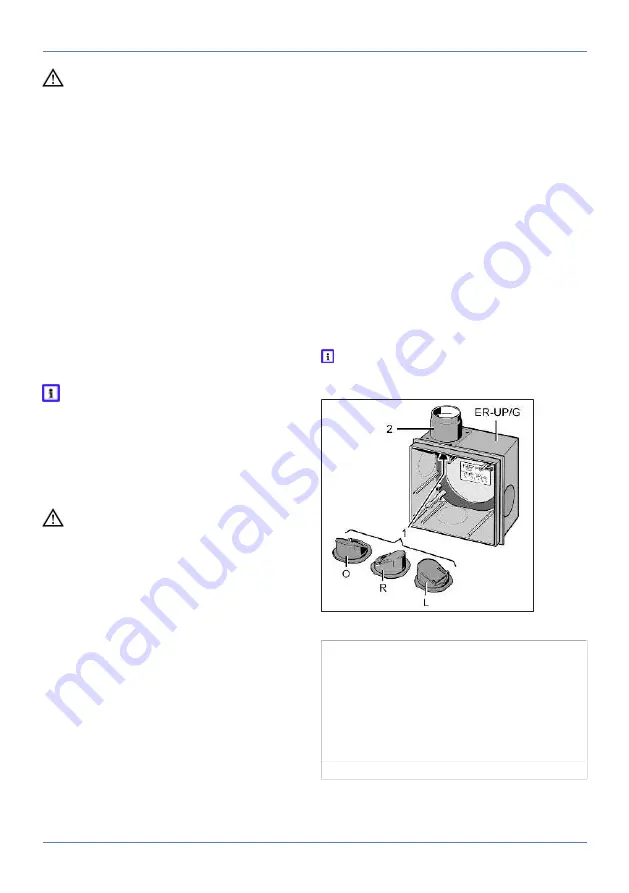
For wall installation with air outlet direction
(exhaust socket) to the
left
or
right
, install the
shutter rotated by 90°, see following figures.
ER-UP/G housing
1 1 Plastic backflow preventer
O: Installation position for upwards air outlet
direction
R: Installation position for right air outlet dir-
ection
L: Installation position for left air outlet direc-
tion
2 2 Plastic exhaust socket


